Relief Valve Hydraulic Symbol

A Guide To Common Hydraulic Symbols Engineeringclicks

Book 2 Chapter 18 Pressure Relief Valves Hydraulics Pneumatics
Reading Fluids Circuit Diagrams Hydraulic Pneumatic Symbols
Basic Hydraulic System Components Parts Design Circuit Diagram

Hydraulic Pneumatic Valve Type Features For Manifolds
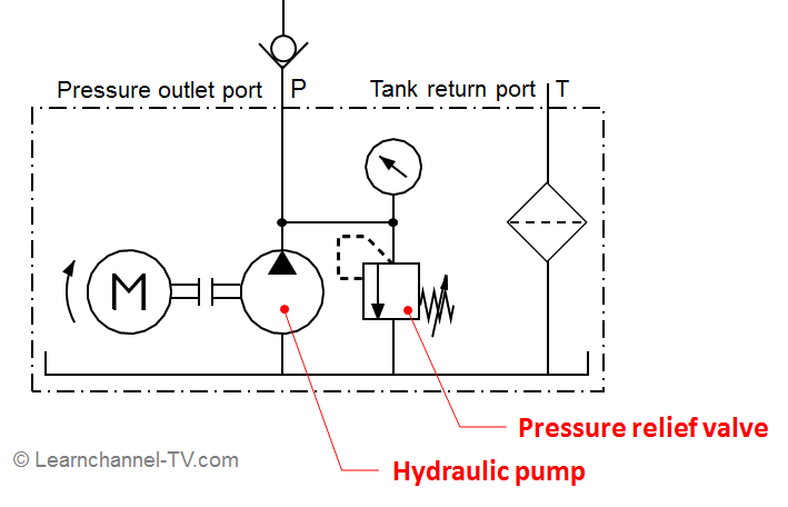
Pressure Relief Valve Learnchannel Tv Com
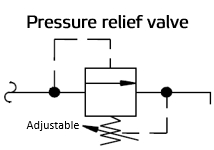
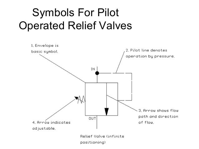
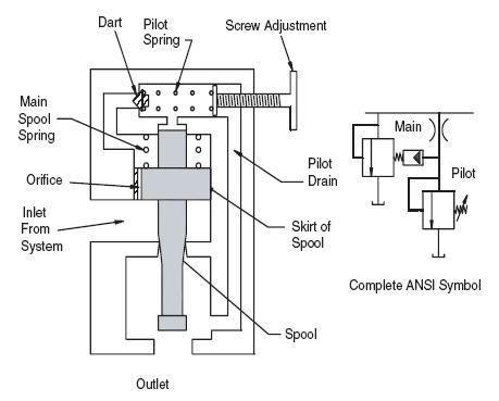
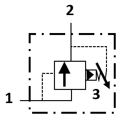
The relief valve in a welldesigned hydraulic circuit never relieves oil to tank — unless there is a circuit or control malfunction Fig 181 Directacting relief valve Figure 181 pictures the symbol for a directacting relief valve A directacting relief valve responds quickly when pressure tries to go above the valve’s setting.

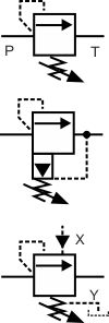
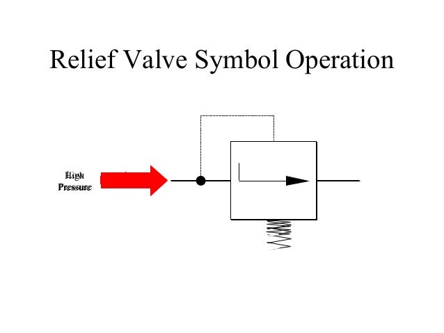
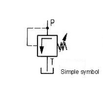
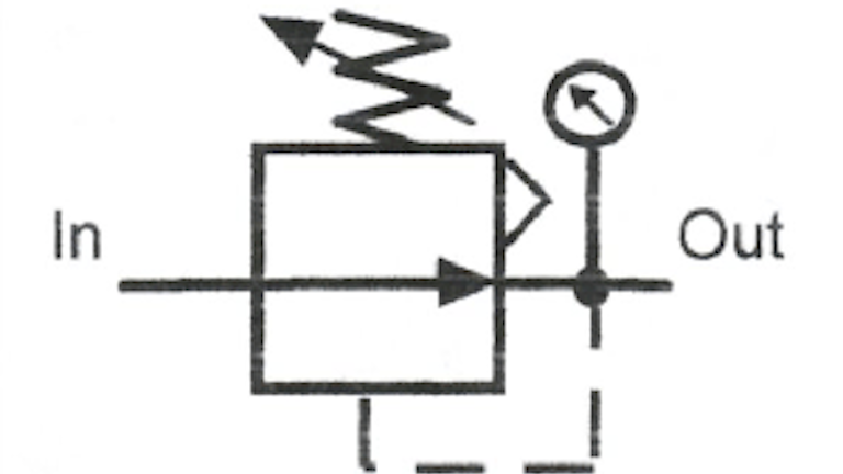
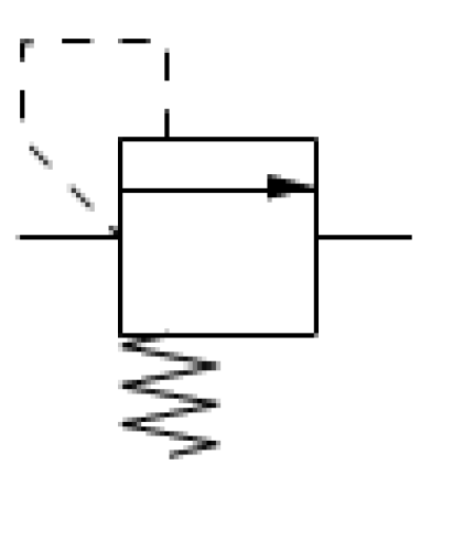
Relief valve hydraulic symbol. Symbol for a relief valve with separate pressure gage The relief valve is spring operated and protects the system from over pressurization It also acts as an unloader valve to relieve pressure when the cylinder is not in operation When system pressure exceeds its setpoint, the valve opens and returns the hydraulic fluid back to the reservoir. Proportional Pressure Relief Valve EPDBD 03 The proportional pressure relief valve, size 03, is a direct operated valve in a differential cone construction It allows pressures to be set proportionally to the solenoid current The EEPDBD 03 is a direct operated valve in which the force of the solenoid acts directly against the hydraulic pressure. The top symbol shows a simple, direct operated pressure relief valve Note how the arrow is shown in it's deactivated position eg with the spring force higher than the pressure in the pilot The pilot pressure also comes straight from the supply line upstream of the valve showing that as the pressure before the valve increases it pushes the arrow against the spring and relieves the pressure.
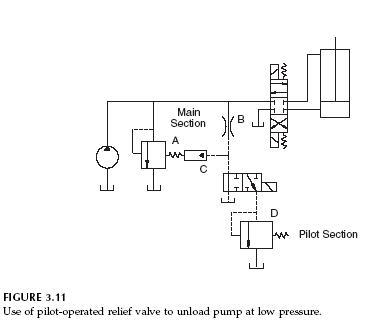
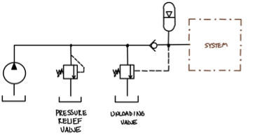
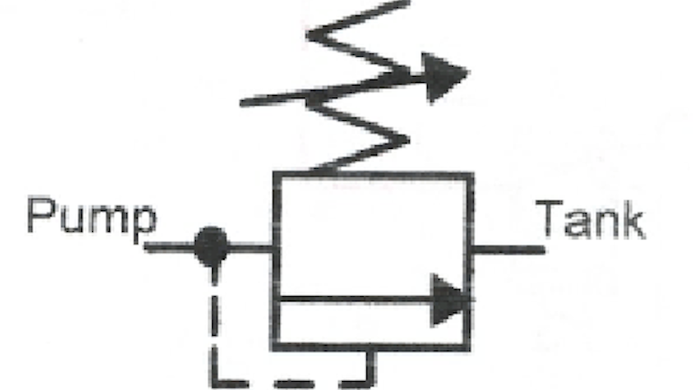
Hydraulic symbols application information hydraulic & offshore supplies basic symbols pressure or return line pilot line two or more functions in one unit flexible hose relief valve pilot operated relief valve sequence valve leakfree sequence valve with external drain relief / unloading valve. Hydraulics Unloading Valve Basic Principle and Symbol The symbol for an unloading valve is similar to the symbol for a relief valve except that the pilot line is not connected to sense pressure at the valve inlet The two symbols are compared in Fig 314 A circuit with an unloading valve is shown in Fig 315. Hydraulic Symbols Hydraulic circuits can be comprised of an infinite combination of cylinders, motors, valves, pumps and other equipment connected via hydraulic pipes and tubes The complexity of these components are difficult to represent fully, so a family of graphic symbols have been developed to represent fluid power components and systems.
Design a valve specifically for your process media and set pressure Choose from a valve for air, inert gas, water, hydraulic oil, fuel oil, gasoline, or diesel fuel and a set pressure from 150 to 3, 300 psi These valves begin opening at the set pressure and fully open at about 10% over the set pressure They begin closing as pressure drops and fully close when the system pressure is restored. The spring rating varies based on how the valve is used in the system One of the most common locations for a check valve is immediately downstream of the hydraulic pump (Figure 2) Notice that no spring is shown with the check valve symbol. Hydraulic Symbols Hydraulic circuits can be comprised of an infinite combination of cylinders, motors, valves, pumps and other equipment connected via hydraulic pipes and tubes The complexity of these components are difficult to represent fully, so a family of graphic symbols have been developed to represent fluid power components and systems.
We’re glad to inform that on October 2 nd an agreement has been reached to transfer 100% ownership of VIS Hydraulics in the hands Relief Valves Bidirectional Symbol. Pressure Relief Valve Reference H1 Component Hydraulic Pressure Relief Valve Category Hydraulic Miscellaneous Stencil Hydraulic Misc s. Valve Technival Information Vacuum Technical Information Actuator Technical Information Fluid Power Graphic Symbols H Technical Data Pneumatic Products Actuator Technical Information Θ ωmax = 035 × t α = ωmax2 Θ =573 W α = ωmax (t ⁄ 2) KE = 1/2 Jm ω2 Ta = α × Jm Tf = W × Us × TL = Torque arm length × WL × cos (φ).
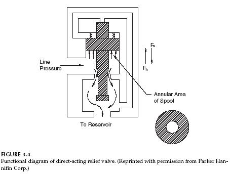
Find a wide array of durable hydraulic valves at Grainger to help run your hydraulic systems efficiently and increase or maintain high productivity Shop here for hydraulic ball valves with your choice of standard and lockable handles, hardseat and softseat pressure control valves and much more. The C175 is suitable for applications requiring an adjustable, small capacity, direct action, springloaded type pressure relief valve or pressure regulating valve It can also be applied as a remote control valve for pilot operation of balanced piston type relief valves The C175 is designed to be panel mounted. Hydraulic Direct Acting Relief Valve A schematic of a directacting relief valve is shown in Fig 34 Pressure acts on the annular area of the valve spool The hydraulic force is given by The notation F s will be used for the spring force When F h equals F s, the valve cracks open, meaning that the spool lifts off its seat and allows fluid to flow to the reservoir As pressure increases, the spool lifts higher, allowing more flow to bypass to the reservoir.
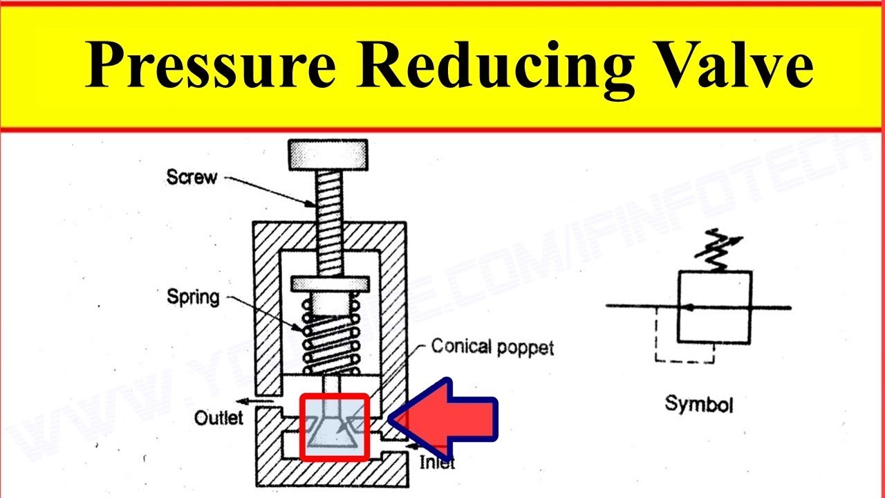
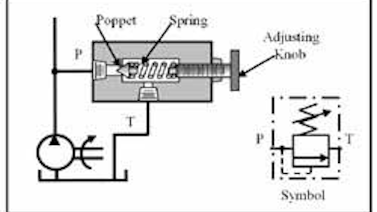
Pressure relief valve will have two sections ie Body section and pilot valve section Body section of relief valve will have a piston which will be retained to its position or seat due to the action of spring force Pilot valve section will control the piston movement with the help of hydraulic force. The most common hydraulic symbols are represented by the ISO standard ;. A relief valve is a last resort safety device and is not intended to be used as a pressure reducing or regulator valve Ports ¾" NPT Inlet Male;.
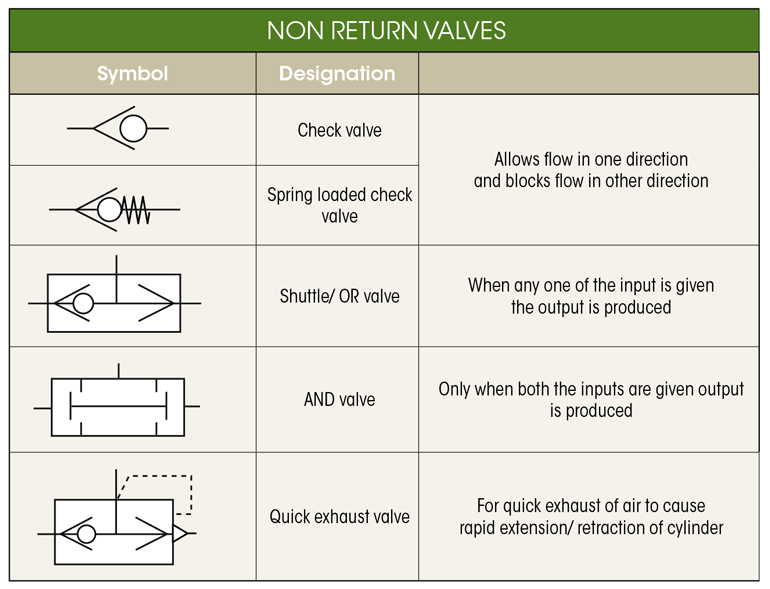
Pressure might otherwise build up and create a process upset, instrument or equipment failure, or fire The pressure is relieved by allowing the pressurized fluid to flow from an auxiliary passage out of the system The relief valve is designed or set to open at a. Hydraulic Schematic Symbolspilot operated check valve, pilot to close pilot operated check valve, pilot to open Shuttle valveto isolate one part of a system from an alternate part of circuit Rapid exhaust valve/Pneumaticinstalled close to an actuator for rapid movement of the actuator Pressure Control Valves Pressure Relief Valve(safety. Pilotoperated, balanced poppet relief valves Pilotoperated, balanced poppet relief valves are similar to other pilotoperated relief valves with several key benefits They can be thought of as a hybrid between a directacting relief and a pilotoperated, balanced piston relief valve.
This valve is derived by combining a small, highperformance 1/8 proportional electrohydraulic pilot relief valve with a specially developed lownoise relief valve With this valve, it is possible to regulate the system pressure in proportion to the input current Note that this valve is used in conjunction with the applicable power amplifier. Valve Technival Information Vacuum Technical Information Actuator Technical Information Fluid Power Graphic Symbols H Technical Data Pneumatic Products Actuator Technical Information Θ ωmax = 035 × t α = ωmax2 Θ =573 W α = ωmax (t ⁄ 2) KE = 1/2 Jm ω2 Ta = α × Jm Tf = W × Us × TL = Torque arm length × WL × cos (φ). As a hydraulics engineer, it's important to understand the difference between valves, even though this may not always be possible from the symbol For example knowing whether the valve uses a sealed poppet, spool element or both can make a big difference to the circuit operation;.
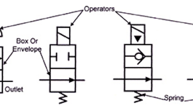
The symbols above are the different ways a valve can be activated electrical solenoid, spring, electrical with a hydraulic pilot, hand emergency, proportional solenoid, manual lever, and a foot. This way the above shown valve is normally closed valve 3 Pressure Relief Valve In hydraulic systems, pressure is generated by pumps But if pumps develop more pressure than the system design pressure, then it may spoil the hydraulic system itself Pressure relief valve protect the system for such cases. If you experience any problems with the site, please contact Pete Hoffman immediately so corrections can be made Pete can be reached on campus, via email at phoffman@swtcedu or by phone at ext 2727.
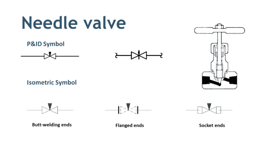
Pressure Relief Valve Reference H1 Component Hydraulic Pressure Relief Valve Category Hydraulic Miscellaneous Stencil Hydraulic Misc s. It's not always added to a relief valve schematic symbol, since many relief valves are cartridge valves and do not have a separate manifold Poppet This arrow represents the relief valve poppet , which allows the valve to crack open when the pressure on the inlet port gets high enough. Many types of valves are required in a process plant for flow regulation or on/off purpose Type of valve employed depends on nature of fluid, flow control required, operating pressure and temperatures as well as surround atmosphere Here is a list of symbols for various types of valves used in process industry.
Using four digits for relief valves and 3 digits for check valves Include leading zeros if necessary For example Relief and Counterbalance Valves 500 psi – 0500 50 psi – 0050 1525 psi – 1525 Check Valves 210 psi – 210 psi 0 3 psi 003 Sandwich Model code information Easy to understand, easy to design RV510(V)* **** **/**. It's not always added to a relief valve schematic symbol, since many relief valves are cartridge valves and do not have a separate manifold Poppet This arrow represents the relief valve poppet , which allows the valve to crack open when the pressure on the inlet port gets high enough. This way the above shown valve is normally closed valve 3 Pressure Relief Valve In hydraulic systems, pressure is generated by pumps But if pumps develop more pressure than the system design pressure, then it may spoil the hydraulic system itself Pressure relief valve protect the system for such cases.
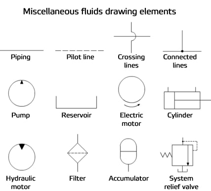
Miscellaneous hydraulic symbols and devices used in hydraulic circuit design Back to symbols Sample Drawings JIC / NFPA Sample Drawing;. IEC Sample Drawing;. Safety Relief Valves SR SRH The SR and SRH Safety Relief Valves are designed to protect industrial and commercial refrigeration systems from overpressure situations This series is designed to open at a specified pressure and can be used in single or dual relief configurations 110 Parts.
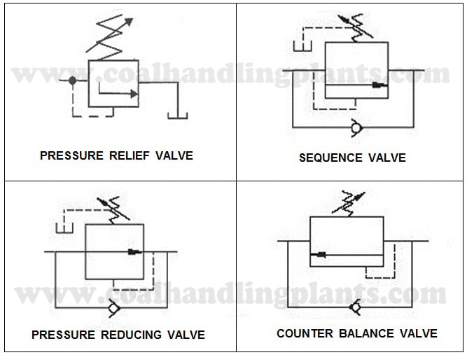
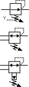
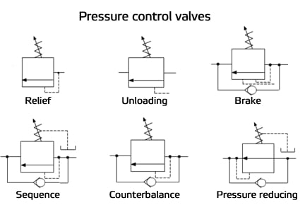
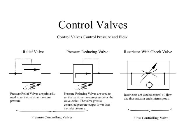
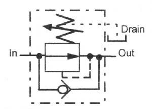
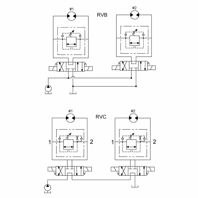
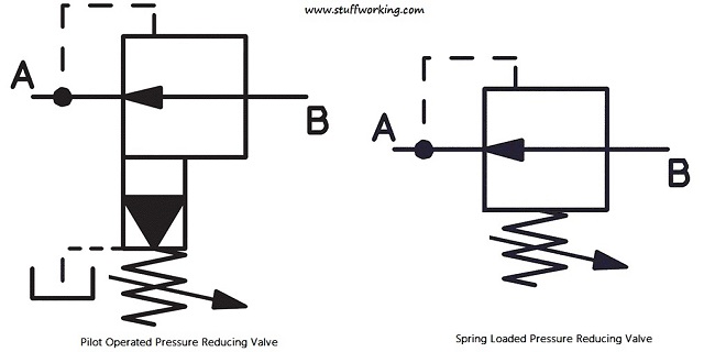
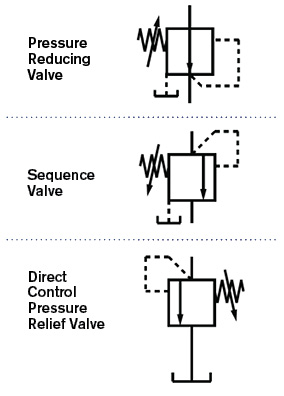
Pressure relief valve A pressure relief valve is a hydraulic component that provides safety to the hydraulic system from excessive pressureThis is normally closed but when the pressure in the hydraulic system increase beyond the set limit of a pressure relief valve, it opens the path and allows hydraulic oil to flow into the tankIn this way, it releases the excessive pressure from the. In hydraulic motor circuits, relief valves can eliminate shock when the motor must be decelerated quickly In this function, fluid is ported from the highpressure outlet port of the motor to the lowpressure inlet port, while holding ample backpressure to stop the motor without damage Fig 911 Symbols for modular relief valves. The pressure reducing valve is the only normally open pressure valve in hydraulics As you can see, it’s very similar to the relief valve, save two changes in the symbol Firstly, the arrow shows it flows in its neutral position, whereas the relief valve is blocked Secondly, it gets its pilot signal from downstream of the valve.
Valve Technival Information Vacuum Technical Information Actuator Technical Information Fluid Power Graphic Symbols H Technical Data Pneumatic Products Actuator Technical Information Θ ωmax = 035 × t α = ωmax2 Θ =573 W α = ωmax (t ⁄ 2) KE = 1/2 Jm ω2 Ta = α × Jm Tf = W × Us × TL = Torque arm length × WL × cos (φ). IEC Sample Drawing;. We’re glad to inform that on October 2 nd an agreement has been reached to transfer 100% ownership of VIS Hydraulics in the hands Relief Valves Bidirectional Symbol.
As the phrase fluid power implies, these symbols cover both hydraulic and pneumatic components Any exceptions are noted Read more about hydraulic symbology in a series from author Josh Cosford Heat exchangers, filters, lubricators and dryers Hydraulic pumps Relief and unloading valves (continued) Directional control valves (continued). The function of a relief valve is to set the maximum pressure in a hydraulic system Although there are many designs and varieties, they can all be denoted by the general symbol (a) in Figure 2 It is a normally closed valve which partially opens permitting flow to the tank port when the pressure at the inlet port overcomes the spring force. It's not always added to a relief valve schematic symbol, since many relief valves are cartridge valves and do not have a separate manifold Poppet This arrow represents the relief valve poppet , which allows the valve to crack open when the pressure on the inlet port gets high enough.
Composite symbols can be devised for any fluid power component by combining basic symbols Simplified symbols are shown for commonly used components 1216 This standard provides basic symbols, which differentiate between hydraulic and pneumatic fluid power media 122 Purpose. Classic hydraulic theory teaches us they do not flow control valves unless and until there is a reverse flow check valve, such as in the last example of Figure 1 The check valve blocks upward flow through this valve symbol, pressing the ball into the seat when flow exists at the bottom port. Outlet Female Cv = Rated Flow = 15 GPM Relief Valve Data Sheet.
Inline Check Valve Hydraulic Spec Sheet Inline Pressure Relief Valve Hydraulic (Metro) Functional Symbol Phone Email CustomerService@Doeringcom Web wwwdoeringcom 2 1 Description Hydraulic Inline Pressure Relief Valve RV Inline Pressure Relief Valve, male/ female design RVF In line Pressure Relief Valve, female/female. CE Marked Relief Valves HiP relief valves are now available with CE marking These products will proudly be marked with the CE symbol, signifying they comply with the stringent requirements of the Pressure Equipment Directive (PED) To order, add CE to your relief valve part number. Relief valve operation, a pilot venting feature allows the system pressure to be dropped to nearzero, or to a lowlevel pressure The valve is available in two versions type ECT5, with integral solenoid operated pilot valve, and in basic form, type ECT In the “ECT5” version, the pilot valve provides for selection of up to three.
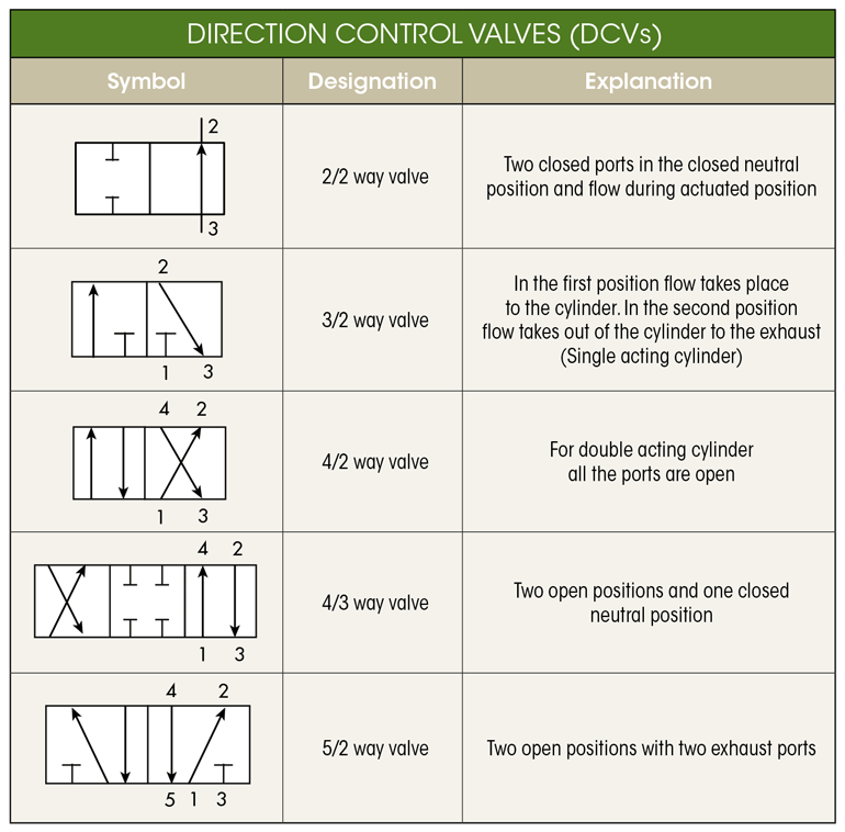
As can pilot feed or orifice positions etc. Directional control valves 4/2way valve with solenoid coil, hydraulic pilot control, reset by spring force Directional control valves 3/2way valve, actuation by roller lever in one direction of travel, spring return, normally closed 6125. A pressure relief valve characterized by rapid opening or closing and normally used to relieve compressible fluids Relief Valve A pressure relief valve characterized by gradual opening or closing generally proportional to the increase or decrease in pressure It is normally used for incompressible fluids Safety Relief Valve.
Symbol Version "C4" Version "K40" General Valves of the KBVS type are pilotoperated proportional pressure relief valves of poppet design and used for limiting the pressure in hydraulic systems They basically consist of a screwedin proportional pilot valve (1) and the main valve (2) These valves can be used for infinitely adusting the pressure. 1 CHECK VALVE NONRETURN VALVE Oil can flow freely from 1 to 2 Oil CANNOT flow from 2 to 1 2 PRESSURE RELIEF VALVE Is used to set the maximum working pressure of the hydraulic system, and therefore the capacity of the lift In example Pmax = 180bar As long as P. Composite symbols can be devised for any fluid power component by combining basic symbols Simplified symbols are shown for commonly used components 1216 This standard provides basic symbols, which differentiate between hydraulic and pneumatic fluid power media 122 Purpose.
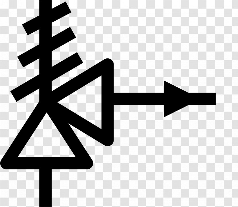
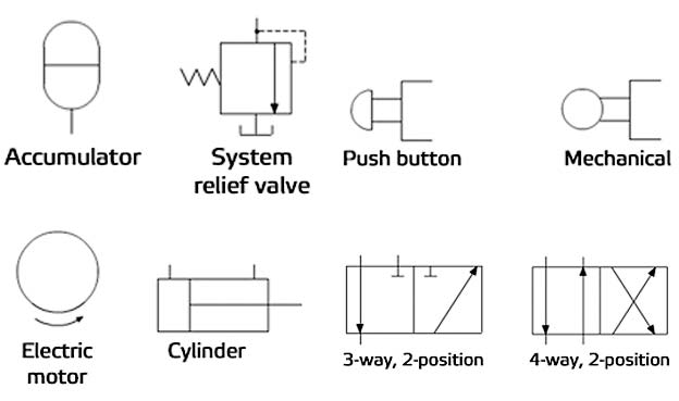
Hydraulic and pneumatic picture symbols for fluid power schematics, define their function in engineering drawings, diagrams, or plans Reference for pictures symbols Airline Hydraulics Pressure Relief Valve (Safety Valve) normally closed Line pressure is limited to the setting of the valve, secondary part is directed to tank. Valve Symbols Valves are used to control the direction, flow rate, and pressure of fluids Figure 1 shows the symbols that depict the major valve types It should be noted that globe and gate valves will often be depicted by the same valve symbol In such cases, information concerning the valve type may be conveyed by the component. The basic valve symbol is a square which represents thebypassed from points of high pressure to points of low pressure valve body or spoolspool An arrow in the center represents the path oil takes through the valve.
A relief valve or pressure relief valve (PRV) is a type of safety valve used to control or limit the pressure in a system;. This page provides the Appendix containing graphic symbols for fluid power diagrams from the US Navy's fluid power training course Other related chapters from the Navy's fluid power training course can be seen to the right. The pressure reducing valve is the only normally open pressure valve in hydraulics As you can see, it’s very similar to the relief valve, save two changes in the symbol Firstly, the arrow shows it flows in its neutral position, whereas the relief valve is blocked Secondly, it gets its pilot signal from downstream of the valve.
The symbols above are the different ways a valve can be activated electrical solenoid, spring, electrical with a hydraulic pilot, hand emergency, proportional solenoid, manual lever, and a foot. Pressure Relief Valve A pressure relief valve is a NC (normally closed) type safety valve which operates when system pressure increases above a maximum working pressure The normally closed position is indicated by the arrow away from the center line. Pilot Operated Pressure Relief Valves Series VBY / VBY*K Working extremely stable and precise, the pilot operated pressure relief valves series VBY and the proportional version series VBY*K in size NG06 and NG10 are particularly suitable for use in machine tools and other applications Configure Product.
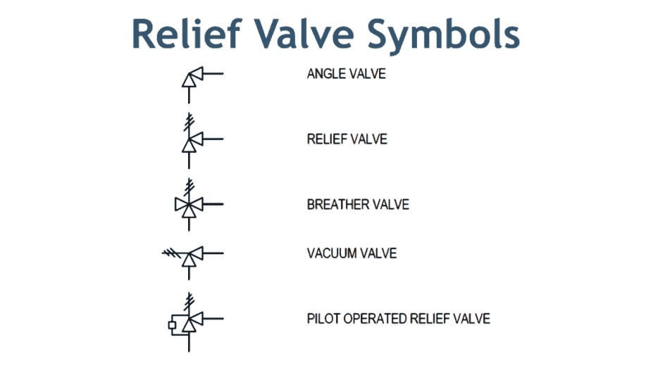
Adjustable DirectlyControlled Pressure Relief Valve Pneumatic Misc. Relief assembly with reverse flow check YCFL Relief assembly with reverse flow check YCFM Relief assembly with reverse flow check YCFN Relief valve assembly with reverse flow check and startup valve YFRC Kick down relief assembly with reverse flow check YQDC Kick down relief assembly with reverse flow check YQFC Triple relief selector assembly YRDC. Relief Valve Symbols Here in the image above, the first symbol is of angle valve In most cases, a globe valve is used as an angle valve The next symbol is of relief valve that used to protect the piping system or equipment from overpressure.
Choose from our selection of pressure relief valves, including fastacting pressurerelief valves, pressurerelief valves, and more In stock and ready to ship.

Understanding Logic Valves In Hydraulic Systems
Hydraulic Symbols Zeus Hydratech
Pressure Relief Valve Symbols

Difference Between Pressure Reducing Valve And Pressure Relief Valve Engineering Made Easy Relief Valve Relief Valve
Q Tbn And9gcrnne1 Iseawvdnarue9f0mgteoqebjmtbud1cyqgmkc4tniyge Usqp Cau

Cartridge Relief Valve Poppet Type Hydraulic Relief Valve Manufacturer
Pilot Operated Relief Valves Hydraulic Circuits Hydraulic Valve

Hydraulic Symbology 2 Stacked And Piloted Industrial Valves

Symbols For Hydraulic Pressure Control Valves
5 3 Pressure Reducing Valves Hydraulics And Electrical Control Of Hydraulic Systems
What S The Difference Between Hydraulic Circuit Symbols Machine Design
Valve Symbols In P Id Ball Valve Relief Valve And More

Hydraulic Symbology 2 Stacked And Piloted Industrial Valves
Control Components In A Hydraulic System Pressure Control Valves Hydraulics And Pneumatics
Hydraulic Symbols Introduction
Hydraulic Symbols Zeus Hydratech
Pressure Relief Valve Symbols

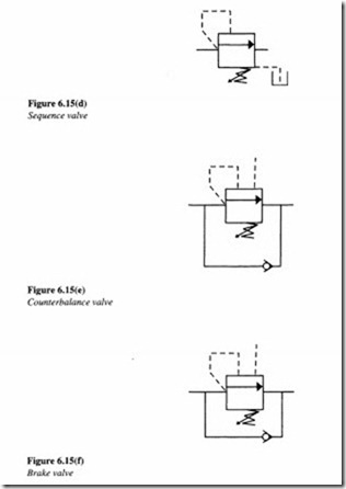
Hydraulic Sequence Valve Operation Engineering Made Easy Relief Valve Hydraulic Systems Valve

The Pilot Operated Pressure Relief Valve

Hydraulic Symbology 2 Stacked And Piloted Industrial Valves

A Guide To Common Hydraulic Symbols Engineeringclicks
Pressure Reducing Valve Working Video In Hydraulic System Youtube
Outline Pressure Relief Valve Symbol Vector Stock Vector Royalty Free

China Proportional Pilot Operated Relief Valve Proportional Valves Hydraulic Control Valve By

Book 2 Chapter 18 Pressure Relief Valves Hydraulics Pneumatics
Reading Fluids Circuit Diagrams Hydraulic Pneumatic Symbols
Hydraulic Symbols Zeus Hydratech
Hydraulic Symbols Introduction
Hydraulic Symbols Understanding Basic Fluid Power Schematics
What Is A Pressure Reducing Valve And How Is It Used In Hydraulics Smith S Hydraulic

What Are Hydraulic Pressure Relief Valves And How To Test Finotek
Relief Valve Safety Gate Piping And Instrumentation Diagram Black White Symbols Transparent Png

Hydraulic Ansi Symbols Flashcards Quizlet

Proportional Pressure Relief Valves Archive Weber Hydraulik

Hydraulic Symbols Parts Gal Industry
Pressure Relief Valve Symbol Icon Royalty Free Vector Image
Design Elements Fluid Power Valves
Q Tbn And9gcqtun4kzwdkqxe4loxy5d7 M8df Sqvlrurmamridk Ltubrbnd Usqp Cau

Hydraulic Symbols Parts Gal Industry

Hydraulic Symbology 3 Pressure Valves

Introduction To Control Valves Symbols
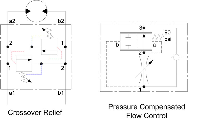
Crossover Relief Valves Related Fluid Power
Pilot Operated Relief Valves Hydraulic Circuits Hydraulic Valve
Hydraulic Direct Acting Relief Valve Hydraulic Valve
Flow Control Valves Hydraulic Symbology 4

Hydraulic Valve Symbols Free Download
5 4 Unloading Valves Hydraulics And Electrical Control Of Hydraulic Systems
Pressure Reduction Valve With Reference To Their Structure And Function
Valve Symbols In P Id Ball Valve Relief Valve And More

What S The Difference Between Hydraulic Circuit Symbols Machine Design
Hydraulics Hydraulics Quiz

Hydraulic Reducing Valve Symbols
Chapter 9 Relief And Unloading Pressure Controls Hydraulics Pneumatics
What S The Difference Between Hydraulic Circuit Symbols Machine Design

Cross Sectional View Of Pressure Relief Valve And Symbol 16 Download Scientific Diagram

Pressure Reducing Valve Symbol Relief Valve Valve Hydraulic Fluid

Rvck Cartridges Pressure Control Relief Sun Hydraulics

Basic Hydraulics
Pressure Reducing Valve Symbol Icon Royalty Free Vector

A Guide To Common Hydraulic Symbols Engineeringclicks

Hydraulics Unloading Valve Basic Principle And Symbol Hydraulic Valve
Http Www Atos Com Tables English C0 Pdf
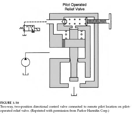
Book 2 Chapter 8 Directional Control Valves Hydraulics Pneumatics
Reading Fluids Circuit Diagrams Hydraulic Pneumatic Symbols

Book 2 Chapter 18 Pressure Relief Valves Hydraulics Pneumatics

Symbol Used In Hydraulic And Pneumatic System Cylinder And Pressure Relief Valve Youtube

Hydraulic Unloading Valve Circuit Operation Hydraulic Valve

Proportional Electro Hydraulic Control Valves Proportional Electro Hydraulic Pilot Relief Valves Hydraulic Schematic Troubleshooting
Pressure Relief Valve Learnchannel Tv Com

Hydraulic Symbology 3 Pressure Valves
Rexroth Pilot Operated Pressure Relief Valve 6 Mpa Back Pressure From China Manufacturer Ningbo Power Hydraulic Motor Co Ltd
Pressure Relief Valve Symbols
Hydraulic Symbology 303 Compound Symbols

Proportional Pressure Relief Valve Epdbd 05 Weber Hydraulik

Difference Between Pressure Reducing Valve And Pressure Relief Valve Engineering Made Easy Relief Valve Valve Hydraulic Systems

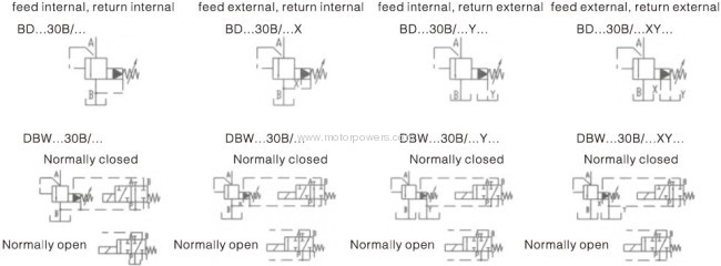
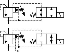
Db Dbw10 Db Dbw Db Dbw30 Polit Operated Pressure Relief Valve

Pressure Reducing Valve Hydraulic Valve
Ape Basic Hydraulics Training
Hydraulic Symbols Fluid Power Engineering Eng Tips
21 Hydraulic Pressure Relief Valve For Hydraulic System Tube Type Relief Valve For Safety High Quality Low Noise From Sharegood 40 21 Dhgate Com
Hydraulic Basics Recognizing Hydraulic Symbols Fluid Power Journal
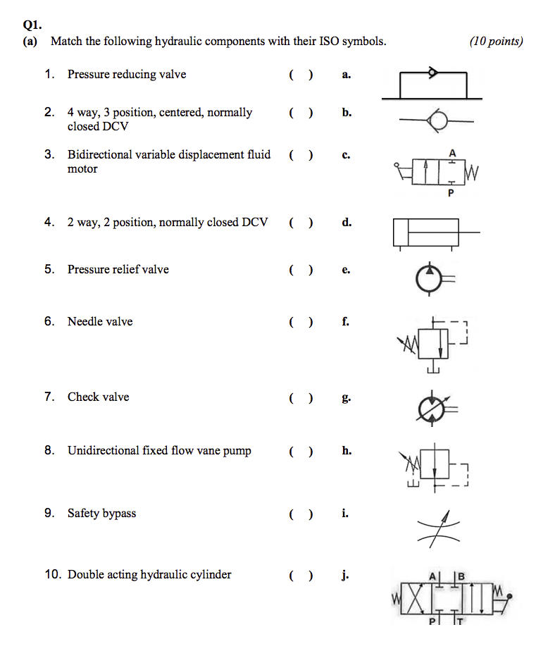
Solved Q1 A Match The Following Hydraulic Components W Chegg Com
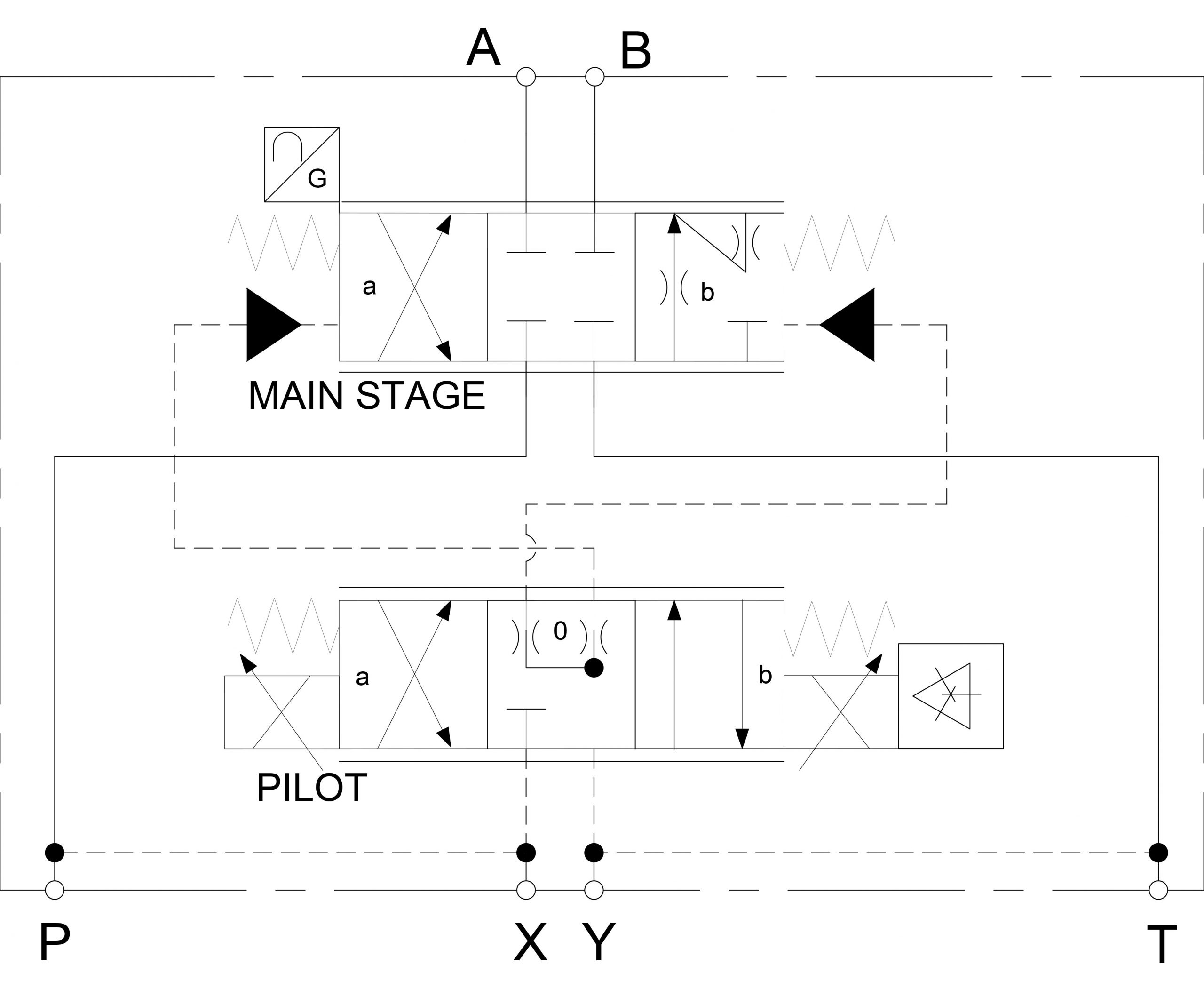
Hydraulic Symbology 302 High Response Valves
Q Tbn And9gcrx8x3vrfw Vspb5lnft Wpckpjn7xlwv8j7dr2hnomivfbtvi0 Usqp Cau

Pressure Control Valves Compound Pressure Relief Valve Hydraulic Schematic Troubleshooting
Pressure Control Valves Hydraulic Pilot Operated Relief Valve Hydraulic Schematic Troubleshooting

Reading Fluids Circuit Diagrams Hydraulic Pneumatic Symbols
Book 2 Chapter 16 Reducing Valves Hydraulics Pneumatics

Hydraulic Pressure Reducing Valve Operation Uses And Types Youtube
Book 2 Chapter 18 Pressure Relief Valves Hydraulics Pneumatics
Hydraulic Symbols Diagram I Fluid Circuit Diagram For Hydraulic System
Common Fluids Valves Explained Cartridge Pressure Relief Valve
5 3 Pressure Reducing Valves Hydraulics And Electrical Control Of Hydraulic Systems

Hydraulic Symbols Understanding Basic Fluid Power Schematics
Pressure Reducing Valve And Pressure Relief Valve Stuffworking Com

Hydraulic Symbols Zeus Hydratech

Pressure Reducing Valve Hydraulic Valve


