Relief Valve Diagram
Bis Valves Products Safety Relief Valve L P Ts25
Differential Relief Valves Related Fluid Power

Test Options For Pressure Relief Valves
Solved How Do A Simple Pressure Relief Valve And A Compound Re Chegg Com

Commonly Used Safety Valves P Id Symbols Enggcyclopedia
Item Rv2150te 1 1 2 Cpvc Pressure Relief Valves W Epdm Seals Threaded End Connections On Hayward Flow Control
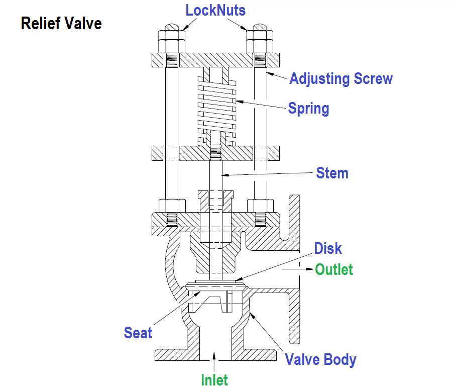
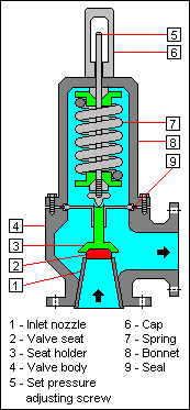
LIQUIFLO Relief Valve Instruction Manual 2 Relief Valve Instructions (Refer to diagram on page 3) Your new Liquiflo Relief Valve is maintenance free The only adjustment on the valve is the resetting of the relieving point This is done by loosening the lock nut (2) and rotating the large cap (1).
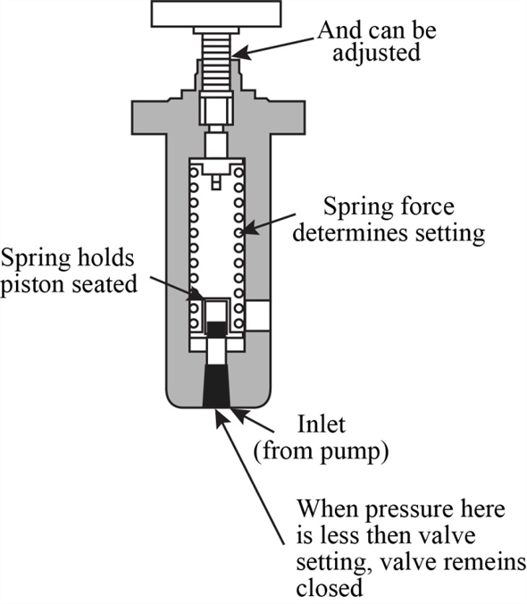
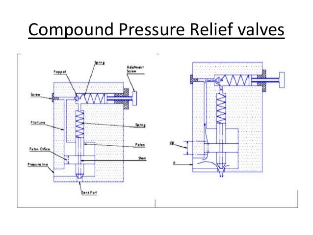
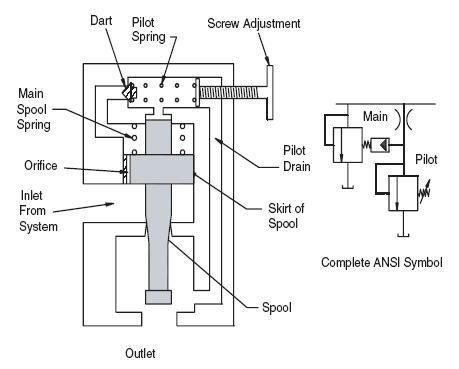
Relief valve diagram. See Product Diagram Below Relief, Backpressure, Bypass & AntiSiphon Valves Prevent system overpressure, regulate backpressure, provide automatic bypass, and eliminate siphon with high performance relief valves 2way and 3way designs, straight and angle pattern, choice of elastomer or PTFE diaphragm design ¼" – 3" sizes Learn More. Hydraulic Valve Division offers both precise and robust pressure relief valves Parker offers a wide array of inline and subplate pressure relief valves for both manual and proportional application requirements. (2) Compound Type Figure 53 shows a compound type relief valve Passage C is used to keep the piston in hydraulic balance when the valve’s inlet pressure is less than its setting (diagram A) The valve setting is determined by an adjusted thrust of spring 3 against poppet 4 When pressure at the valve’s inlet reaches the valve’s setting.
The vacuum valve prevents damage to the equipment from negative pressure Pilot operated relief valve are just working as a relief valve, but are used for large size piping In this type, a small relief valve is used to operate the main relief valve This arrangement is costeffective in the large size relief operation. 18 Highpressure relief valve and drain 19 Highpressure injector supply lines Highpressure fuel connector 21 Fuel injector 22 Fuel injector drain check valve (banjo type) 23 Fuel drain from injector 24 Fuel drain manifold 25 Fuel retrofit thermal recirculation valve 26 Fuel pump drain 27 Fuel return to tank. CONTROL VALVE DOES NOT CENTER (Binding) See Hydraulic Product Safety sheet Valve linkage misaligned Repair Tiebolts too tight (stack valves) Loosen as necessary Valve damaged Repair or replace Handle bracket screws loose Tighten CONTROL VALVE LEAKS EXTERNALLY Tiebolts too loose (stack valves) Tighten as necessary Seals damaged or.
Hale Products is committed to offering the highest level of service and performance for rescue personnel and fire truck manufacturers Consisting of three brands Hale, Class 1 and Godiva, Hale Products is a leader in fire suppression pumps, plumbing, valves, foam, CAFS, electronic, gauges and ESkey multiplexing systems. BYPASS Relief Valve( p/n) 30 gpm x 0500 psi $1, FMC Rod Kit $ FMC Inner Spring For P , P5109 & Rel Valves $3600. Anderson Greenwood Series 0/400/500/700/800 Pilot Operated Relief Valves.
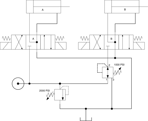
Video describes how the Waterous Discharge Relief Valve Operates. The relief valve typically dumps back into the reservoir Most relief valves are infinitely variable PRESSURE RELIEF VALVE Pressure Relief Valve Reading and Interpreting Hydraulic Schematic Symbols Page 13 Sullivan Sequence Valve A sequence valve is a normally closed valve that opens once the inlet pressure reaches a pre. The Waterous Intake Relief Valve system is designed to act as a safety valve by "dumping" excess pressure from the inlet side of the pump The Discharge Relief Valve provides sensitive pump control to protect firefighters from sudden pressure surges resulting from changes in discharge flows from the pump.
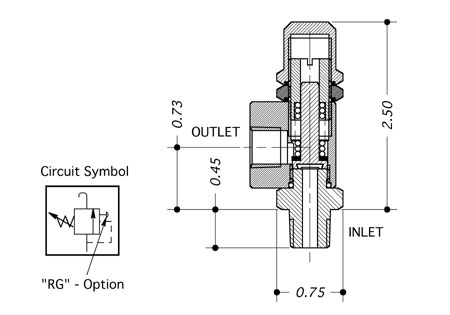
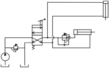
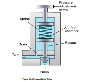
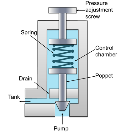
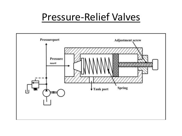
T Combines a service line valve, a back check filler valve, with secondary back check, a relief valve, and a fixed maximum liquid level gauge (must specify liquid level tube length when ordering) t Lightweight and compact t Ideal for onsite filling of DOT cylinders up to 4 lb capacity without interrupting service. Symbol for a relief valve with separate pressure gage The relief valve is spring operated and protects the system from over pressurization It also acts as an unloader valve to relieve pressure when the cylinder is not in operation When system pressure exceeds its setpoint, the valve opens and returns the hydraulic fluid back to the reservoir. Schematic diagram of simple relief valve is shown in Fig 11 and threedimensional view is shown in Fig 12 It is normally a closed valve whose function is to limit the pressure to a specified maximum value by diverting pump flow back to the tank A poppet is held seated inside the valve by a heavy spring.
PL742 TPM Relief Valve System pdf Fire Pumps PL743 TPM System Tubing and Wiring Diagram pdf Fire Pumps PL3 Dual TPMP40 RV System Tubing and Wiring Diagram pdf Fire Pumps PL930 TPM Relief Valve System FDNY OBSOLETE pdf. If a pressure relief valve for a boiler is accidentally installed on a water heater, it will leak like crazy from the start These valves may look identical, but they’re set to go off at 30 psi. Create a siphon and drain a tank The valve is set to open at the desired pumping pressure, but seals tightly when a vacuum occurs downstream IV WHY would I use a Relief Valve versus some other comparable valve?.
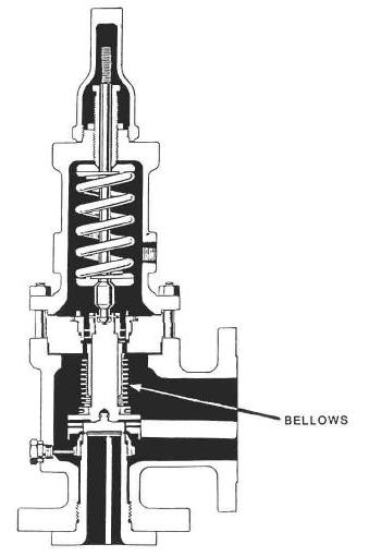
· Relief, Flanges and safety valves P&ID – P&ID have general notes that will assist during Detailed Engineering, Erection and Commissioning phase, A great deal of information can be represented. Taylor Valve Technology is a leading manufacturer of high quality safety relief, high pressure relief, and back pressure relief valves Taylor Valve also offers a wide array of choke and control valves, and pilot operated valve products for the oil and gas industry Every Taylor Valve product is designed to meet the highly demanding. The configuration shown on the flow diagram must always be followed Relief valve systems designed to discharge against a constant pressure cannot tolerate a back pressure greater than 10% of the set pressure Balanced bellows or Balanseal type relief valves which operate practically independent of the back pressure tolerate a much higher.
If a pressure relief valve for a boiler is accidentally installed on a water heater, it will leak like crazy from the start These valves may look identical, but they’re set to go off at 30 psi. The general relief valve does not pass in the reverse direction 4) Bidirectional type In the hydraulic motor drive circuit, the pressure relief valve, or a twoway relief valve, should generally be installed on both sides to prevent excessive pressure on one side due to external loads during neutral conditions 5) External control type. The relief valve typically dumps back into the reservoir Most relief valves are infinitely variable PRESSURE RELIEF VALVE Pressure Relief Valve Reading and Interpreting Hydraulic Schematic Symbols Page 13 Sullivan Sequence Valve A sequence valve is a normally closed valve that opens once the inlet pressure reaches a pre.
A stop valve 92 A pressure relief valve shall be set to function at a pressure not in excess of 250 PSI 93 Pressure relief valves shall discharge into the low pressure side of the refrigerating system or to the outside of the building A pressure relief valve discharging into the lowpressure side must be of the type that is not affected by. A lot of hydraulic problems are caused by blocked filters and in turn jammed or broken filter bypass valves This video runs through how to check your transm. A relief valve functions by discharging water, it is essential that a discharge line be piped from the valve in order to carry the overflow to a safe place of disposal The discharge line must be the same size as the valve outlet, and must pitch downward from the valve.
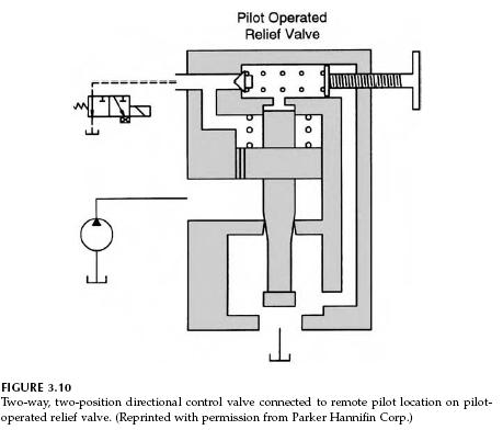
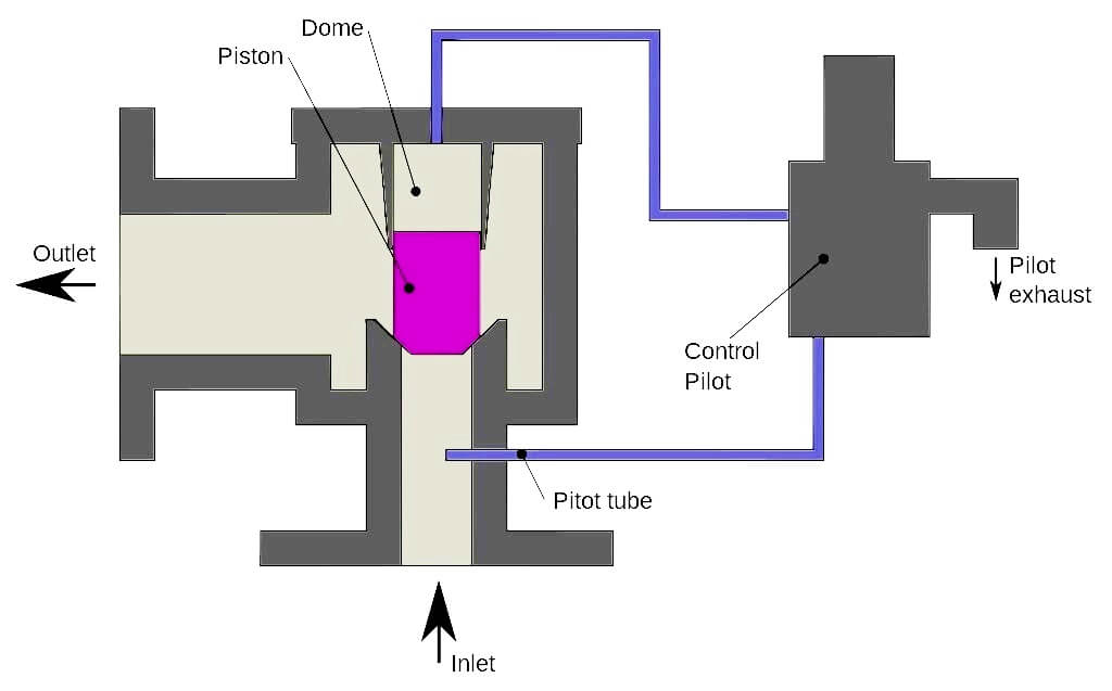
Hydraulic Valves & Accessories This page is part of a complete catalog which contains technical and safety data that must be reviewed when selecting a product. The relief valve shown in Figure 6 includes a pitot tube to reduce pressure buildup When the valve is opening, high gas velocity through the seat ring creates an area of relatively low pressure Low pressure near the end of the pitot tube draws gas out of the volume above the relief valve diaphragm and creates a partial. Controls the operation of the relief valve proper, and the relief valve which is normally mounted on the pump The pilot valve has two controls, one to adjust the relief valve operating pressure, and the other, an ONOFF con‐ trol, to place the relief valve in or out of operation The ONOFF control lets the operator put the relief valve.
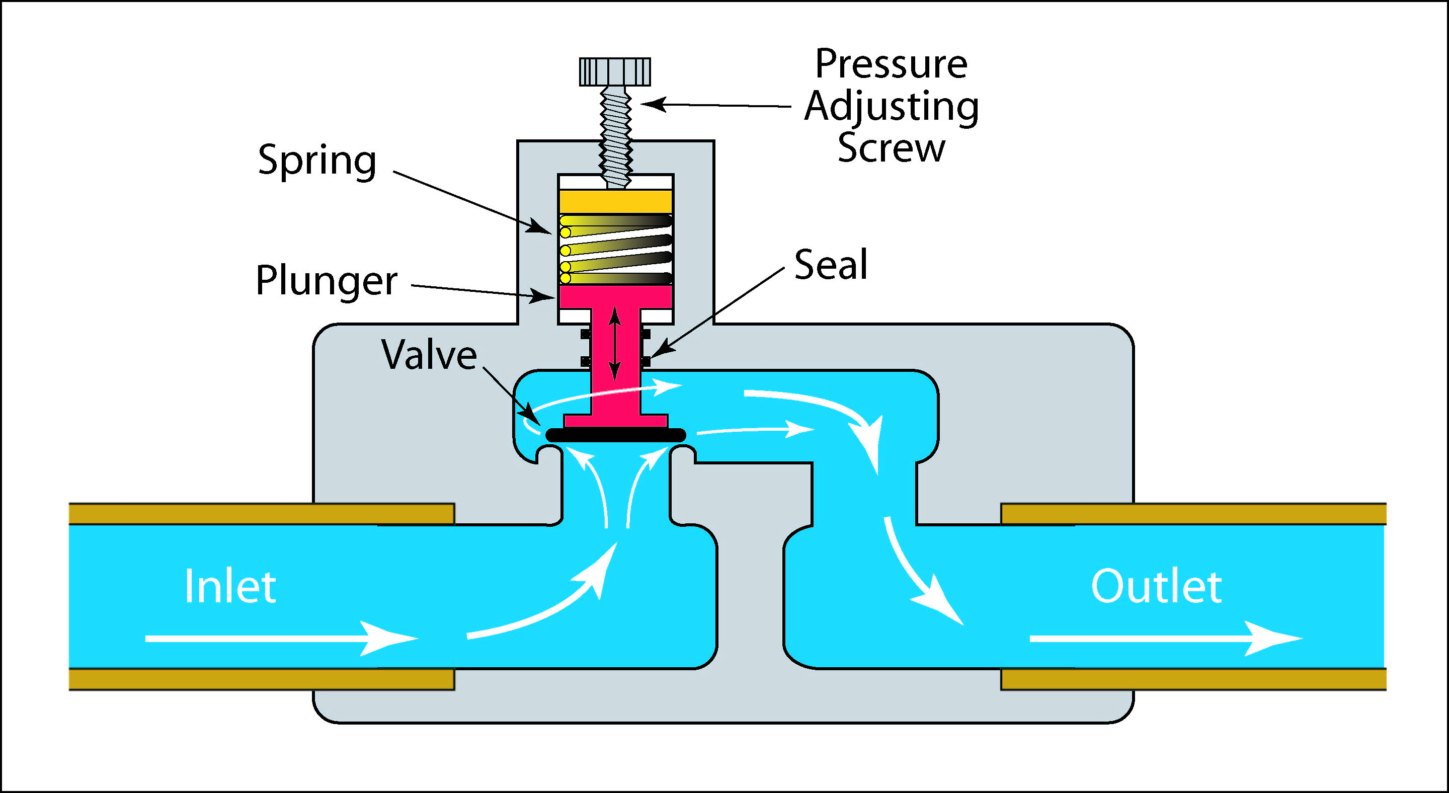
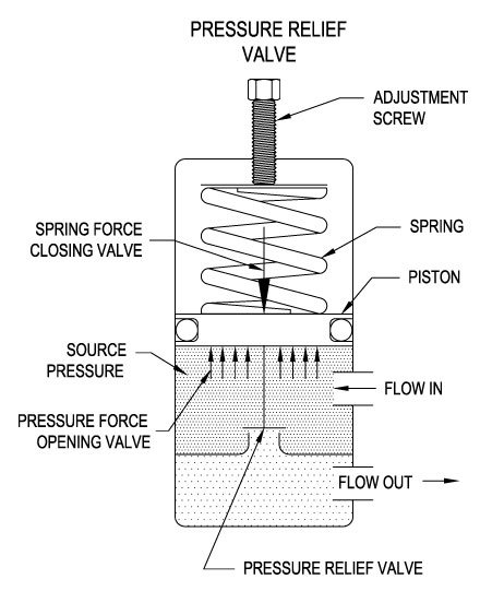
CAD Drawing & Diagrams Drawings Center Liquid Analysis Wiring Diagram AVENTICS CAD search See All Calculators Multiphase Flow Calculator Anderson Greenwood Series 0/400/500/700/800 Pilot Operated Relief Valves;. Searching for APOLLO Relief Valves?. Pressure might otherwise build up and create a process upset, instrument or equipment failure, or fire The pressure is relieved by allowing the pressurised fluid to flow from an auxiliary passage out of the system The relief valve is designed or set to open at a.
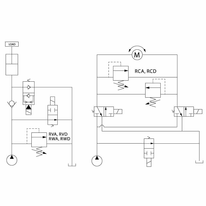
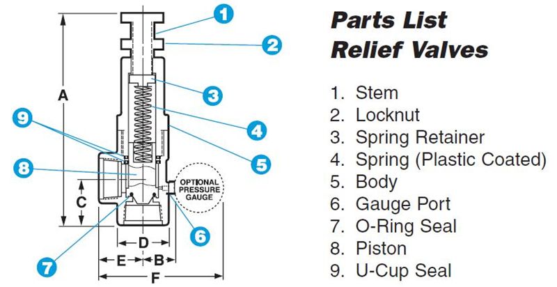
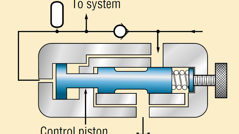
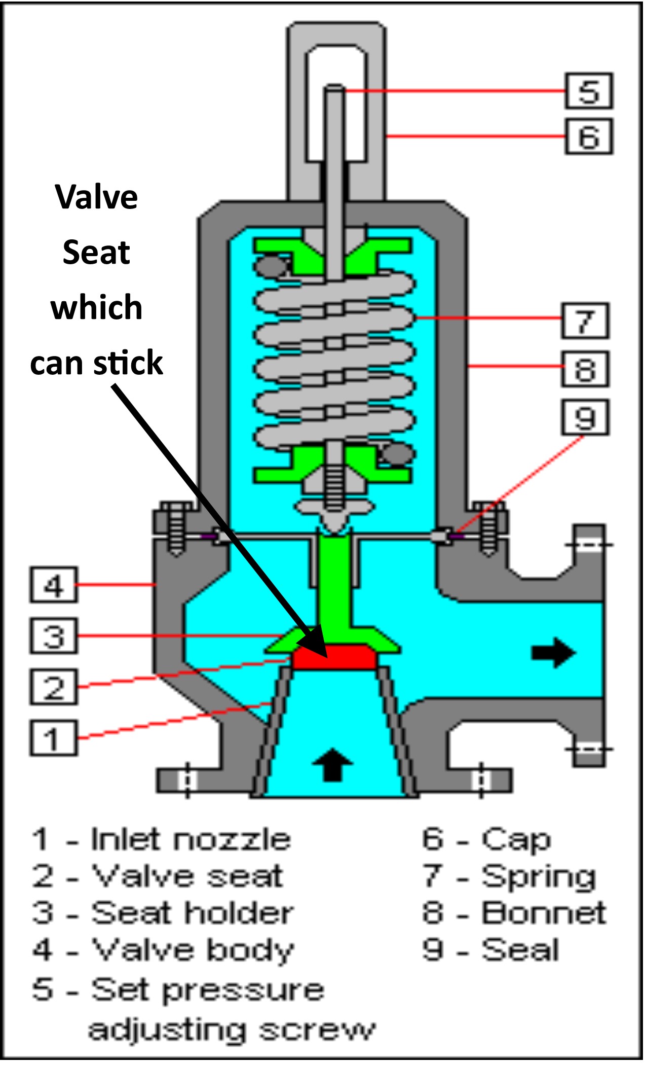
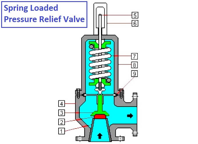
The relief valve is fully open or vented because the control piston pushes the pilot control piston off its seat Without a control piston, relief valves relieve excess pump flow at set pressure, generating a lot of heat This unloading relief valve has a preset differential of 15% between unloading and reloading the pump Fig 19. (1) VALVE ELEMENT (poppet valve) Most commonly, pressure relief valves employ a spring loaded “poppet” valve as a valve element The poppet includes an elastomeric seal or, in some high pressure designs a thermoplastic seal, which is configured to make a seal on a valve seat. As shown in the application diagram above, this is a very versatile and widely utilized valve.
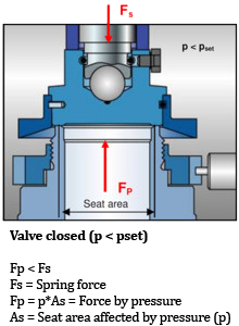
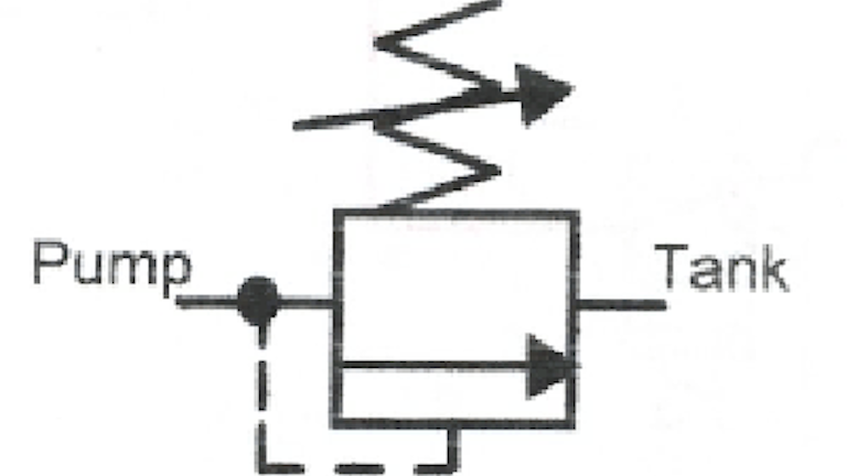
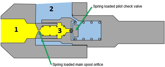
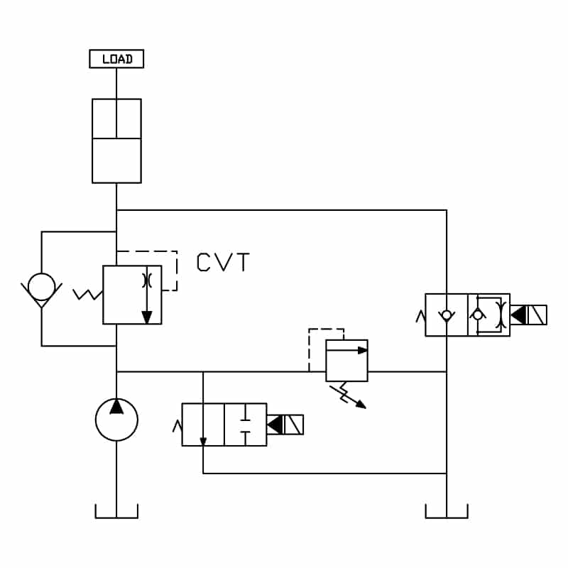
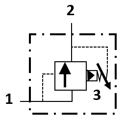
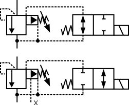
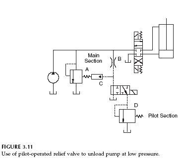
A pressure relief valve is a NC (normally closed) type safety valve which operates when system pressure increases above a maximum working pressure The normally closed position is indicated by the arrow away from the center line The dashed line indicates that the system pressure acts against spring force for valve actuation. DIRECT SPRING PRESSURE RELIEF VALVES SEAT DESIGN Series JOSE and JBSE relief valves are available with flat metaltometal or soft seats Their twopiece disc holder/disc insert construction provides thermal balancing assuring maximum seat tightness and meets the requirements of API Standard 527, ‘Seat tightness of pressure relief valves’. A diagram of a circuit that uses a pilotoperated relief valve to unload the pump at low pressure is shown in Fig 311 The relief valve symbol designated with the letter “A” refers to the main spool of the pilotoperated relief valve.
Pressure relief valve installation Mounting Mount PRVs in a vertical position, which means upright and with the spindle vertical A valve installed in any position other than vertical might not perform correctly For flanged valves, be sure to draw the bolts down evenly This is especially crucial for cast iron valves. Pilot Operated Pressure Relief Valve Series R4V (Denison) 10 R4V_UKINDD RH_1917 Characteristics Pilot operated pressure relief valves for inline mounting series R4V have a similar design to the subplate mounted R4V series For single functions where no manifold blocks are used the valves can be directly placed in the pipework. Check the relief valve to see whether it is partially left open and close it in case it is open To troubleshoot John Deere tractor hydraulics, check if the boom arms are binding at the pivots, making sure that the arms rise and lower correctly Remember to lubricate the linkage if you establish that this is necessary.
Pressure relief valve installation Mounting Mount PRVs in a vertical position, which means upright and with the spindle vertical A valve installed in any position other than vertical might not perform correctly For flanged valves, be sure to draw the bolts down evenly This is especially crucial for cast iron valves. Pressure Relief Valve Check Valve Cold Water Isolator Valve Assembly Hot Water Isolator Valve Assembly Tankless Water Heater Installation Diagrams Tankless Installation / Optional Return Circulation °F PRIORITY POWER ON/OFF QQQ)QQQ This drawing is intended as a guide only It is not to be used as an alternative to. 3 Temperature and pressure relief valves shall be installed so that the sensing element of the valve extends into the heater tank and monitors the temperature in the top 6 inches of the heater or tank 5 Every relief valve which is designed to discharge water or steam shall be connected to a discharge pipe.
Program for pressure relief valves, PRV2SIZE (Pressure Relief Valve and Vent Sizing Software) The use of this comprehensive program allows an accurate and documented determination of such parameters as pressure relief valve orifice area and maximum available flow This sizing program is a powerful tool, yet easy to use Its many. Symbol for a relief valve with separate pressure gage The relief valve is spring operated and protects the system from over pressurization It also acts as an unloader valve to relieve pressure when the cylinder is not in operation When system pressure exceeds its setpoint, the valve opens and returns the hydraulic fluid back to the reservoir. A lot of hydraulic problems are caused by blocked filters and in turn jammed or broken filter bypass valves This video runs through how to check your transm.
If a pressure relief valve for a boiler is accidentally installed on a water heater, it will leak like crazy from the start These valves may look identical, but they’re set to go off at 30 psi. Hansen EZSRV Cartridge Pressure Relief valves protect refrigeration pressure vessels and other refrigeration system components from excessive pressure If an abnormally high pressure occurs, the cartridge pressurerelief valve will open to relieve the excess pressure, preventing potential damage to equipment and injury to personnel. Hydraulic Valves & Accessories This page is part of a complete catalog which contains technical and safety data that must be reviewed when selecting a product.
A relief valve or pressure relief valve (PRV) is a type of safety valve used to control or limit the pressure in a system;. Pressure relief valve installation Mounting Mount PRVs in a vertical position, which means upright and with the spindle vertical A valve installed in any position other than vertical might not perform correctly For flanged valves, be sure to draw the bolts down evenly This is especially crucial for cast iron valves. The relief valve typically dumps back into the reservoir Most relief valves are infinitely variable PRESSURE RELIEF VALVE Pressure Relief Valve Reading and Interpreting Hydraulic Schematic Symbols Page 13 Sullivan Sequence Valve A sequence valve is a normally closed valve that opens once the inlet pressure reaches a pre.
A relief valve functions by discharging water, it is essential that a discharge line be piped from the valve in order to carry the overflow to a safe place of disposal The discharge line must be the same size as the valve outlet, and must pitch downward from the valve. Grainger's got your back Easy online ordering for the ones who get it done along with 24/7 customer service, free technical support & more. The vacuum valve prevents damage to the equipment from negative pressure Pilot operated relief valve are just working as a relief valve, but are used for large size piping In this type, a small relief valve is used to operate the main relief valve This arrangement is costeffective in the large size relief operation.
Choose from our selection of relief valves, including fastacting pressurerelief valves, pressurerelief valves, and more In stock and ready to ship.
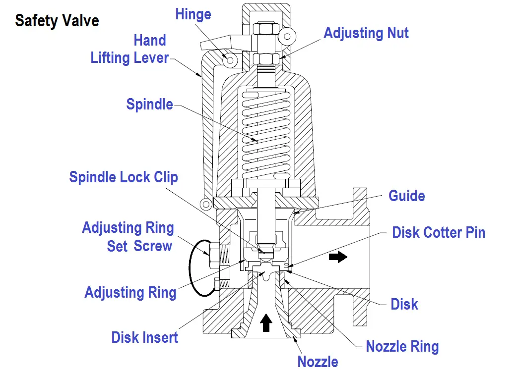
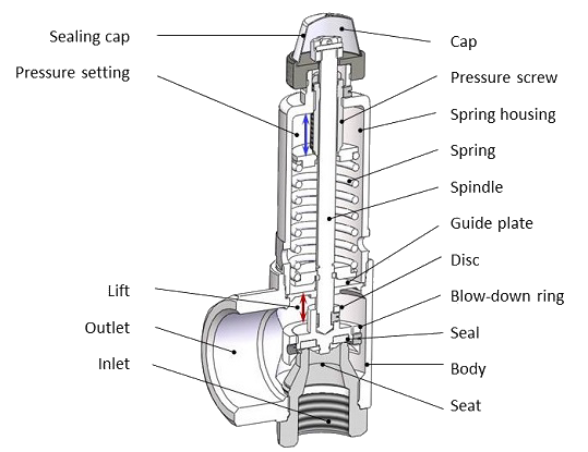
Safety Valve Tutorial Spring Loaded Safety Valve

Difference Between Psv And Prv Ishanee S Blog
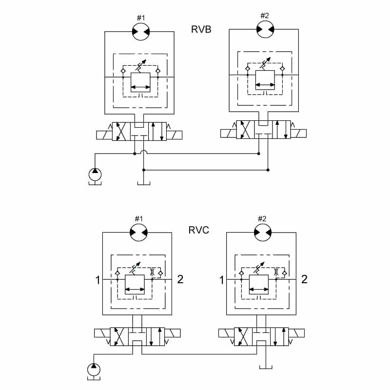
Pilot Operated Relief Valves Hydraulic Circuits Hydraulic Valve
Relief Valves For Hydraulic Circuit Bezares Sa

Pressure Level Relationships For Pressure Relief Valve Courtesy Of Download Scientific Diagram
Q Tbn And9gcrnne1 Iseawvdnarue9f0mgteoqebjmtbud1cyqgmkc4tniyge Usqp Cau
Balanced Bellows Relief Valves Oil Gas Industry Technology Updates
Book 2 Chapter 18 Pressure Relief Valves Hydraulics Pneumatics
Compare Relief Valve And Safety Valve Safety Valve Versus Relief Valve

Safety Valve Sgi

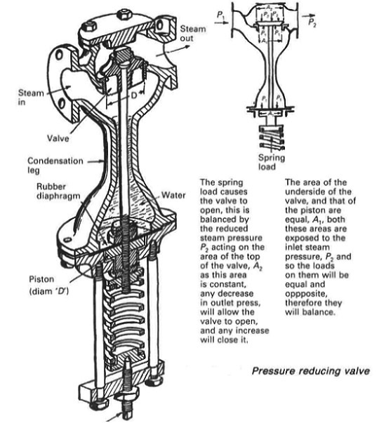
Pressure Reducing Valve Hydraulic Valve
Common Fluids Valves Explained Cartridge Pressure Relief Valve
Valves Backpressure Regulating Valves Ctg Technical Blog
The Lowdown On Pressure Reducing Valves
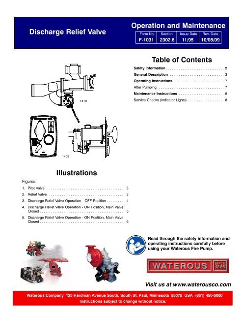
Sec 2302 6 Discharge Relief Valve Operation Instructions Waterous

Pressure Control Valves Compound Pressure Relief Valve Hydraulic Schematic Troubleshooting

Cross Section Of A Conventional Relief Valve Courtesy Of Api Download Scientific Diagram

Relief Valves An Overview Sciencedirect Topics
Pilot Operated Relief Valve Principle Porv Valve Principle
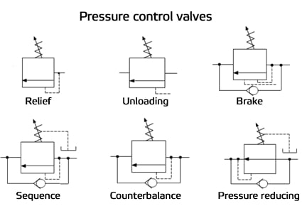
Understanding Pressure Control Valves Hydraulics Pneumatics
Www Emerson Com Documents Automation Pressure Relief Valve Engineering Handbook En Us Pdf

Book 2 Chapter 18 Pressure Relief Valves Hydraulics Pneumatics

Book 2 Chapter 18 Pressure Relief Valves Hydraulics Pneumatics
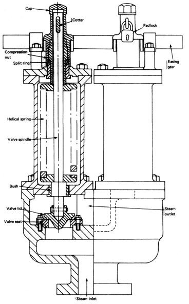
Boiler Safety Relief Valve Setting And Construction Explained Bright Hub Engineering
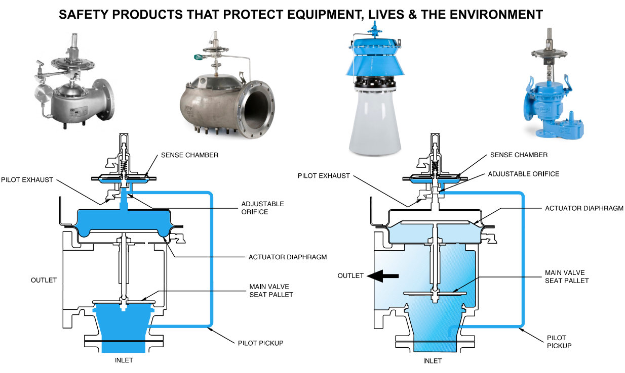
Pilot Operated Relief Valve Working Principles And Advantages Assentech Limited

Differential Pressure Relief Valve Tech Briefs

The Pressure Relief Valve In The Motor Circuit
John Curtin Home Inspector Water Heater Pressure Relief Valve

Relief Valve Wikipedia

Dual Crossover Hydraulic Relief Cushion Valve 3 4 Npt Ports 30 Gpm
5 3 Pressure Reducing Valves Hydraulics And Electrical Control Of Hydraulic Systems
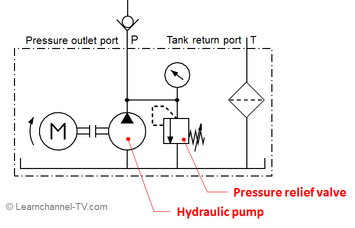
Pressure Relief Valve Learnchannel Tv Com
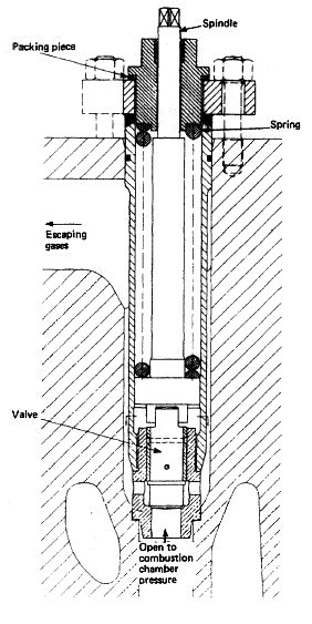
Cylinder Relief Valve For Marine Diesel Engine
Pressure Relief Valves Empowering Pumps And Equipment

Flow Control Valves Hydraulic Relief Valves Hydraulic Schematic Troubleshooting

When Safety Relief Valves Fail To Provide Safety Or Relief At Nuclear Plants Union Of Concerned Scientists

Diagram Of A Safety Valve 07 Yamaha Golf Cart Wiring Diagram Begeboy Wiring Diagram Source
Check With Thermal Relief Valves Related Fluid Power
Pressure Control Valves
Www Waterousco Com Media Wysiwyg Pdfs Accessories Pressure Control Sec3010 Pdf
Bis Valves Products Cartridge Relief Valve L P Ts25c
Common Fluids Valves Explained Cartridge Pressure Relief Valve

Safety Relief Valves Flowstar Uk Limited

Pressure Reducing Valve Hydraulic Valve

Marine Education
Relief Valves Pressure Reducing Valves Ship Service Systems
Hydraulic Systems Pressure Relief Valves
What Is Pressure Relief Valve Pressure Relief Valve Prv Principle

Book 2 Chapter 18 Pressure Relief Valves Hydraulics Pneumatics
Safety Valves Solidswiki
Pressure Relief Valve Symbols
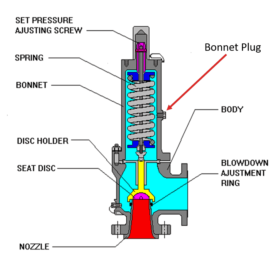
Diagram Of Safety Valve Vauxhall Engine Diagram Begeboy Wiring Diagram Source

Cross Section Of A Pilot Operated Relief Valve Download Scientific Diagram
Pilot Operated Relief Valves Hydraulic Circuits Hydraulic Valve
Q Tbn And9gctmdtfiaqftif8fvfyavoite6iwxsof7wiwkckd6oevdocd2ib Usqp Cau
Pressure Relief Valve Working Principle And Its Internal Construction Mechanical Engineering Concepts And Principles

Sketch Of The Modelica Model Of A Compound Relief Valve Download Scientific Diagram

Pneumatics Lab 6a And Circuit Using The Two Pressure Valve Youtube

Safety Relief Valves Flowstar Uk Limited

When Safety Relief Valves Fail To Provide Safety Or Relief At Nuclear Plants Union Of Concerned Scientists

Safety Relief Valve A Pressure Relieving Device Relief Valve Safety Valve Valve

Single Stage Pressure Relief Valve With Components Download Scientific Diagram

Hydraulic Pressure Relief Valve Is Assembled And Tested Via Emap Promess Inc
Compare Relief Valve And Safety Valve Safety Valve Versus Relief Valve

Hydraulic Symbology 3 Pressure Valves
Crossover Relief Valves Related Fluid Power

Conventional Relief Valves Oil And Gas Separator

How Auxiliary Relief Valve Protects Hydraulic Ram In Circuit Must Watch Youtube

The Studied Pressure Relief Valve Download Scientific Diagram

P Id Guidelines For Pressure Safety Valves Safety Valve Valve Pressure

Engineering Essentials Pressure Control Valves Hydraulics Pneumatics

Hydraulic Pressure Reducing Valvesmodern Industrial Hydraulics Modern Industrial Hydraulics

Spring Loaded Psv Model A Spring Loaded Pressure Safety Valve Is A Download Scientific Diagram
A Schematic Representation Of A Pressure Relief Valve Connected To A Download Scientific Diagram

Relief Valves
Reading Fluids Circuit Diagrams Hydraulic Pneumatic Symbols

Pilot Operated Pressure Relief Valves

Pilot Operated Relief Valves Oil And Gas Separator
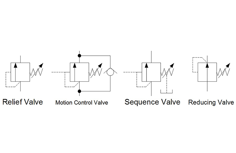
Hydraulic Symbology 3 Pressure Valves
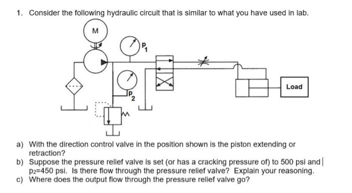
Solved 1 Consider The Following Hydraulic Circuit That I Chegg Com

Direct Acting And Pilot Operated Pressure Relief Valve Operation Youtube

Overpressure Protection Devices Industrial Process Safety And Instrumentation Automation Textbook

Schematic Showing Operation Of A Balanced Bellows Relief Valve Download Scientific Diagram

Relief Valves An Overview Sciencedirect Topics
Pressure Control Valves Hydraulic Pilot Operated Relief Valve Hydraulic Schematic Troubleshooting
Q Tbn And9gcqukjkk4ynvugmqa7mczauebgcles4hvw7zvwqiu Ezo7o5jaqk Usqp Cau
Pressure Control Valves

Pressure Control Valves Hydraulic Direct Acting Relief Valve Working Principle Hydraulic Schematic Troubleshooting
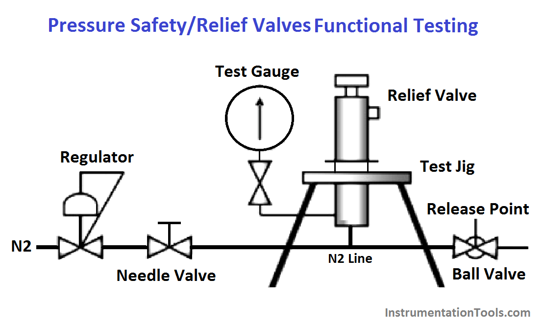
Pressure Safety Valves Functional Testing Instrumentationtools

Pilot Operated Relief Valve Wikipedia
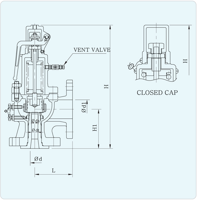
Full Bore Safety Relief Valve Ynv English
3

What Are Hydraulic Pressure Relief Valves And How To Test Finotek
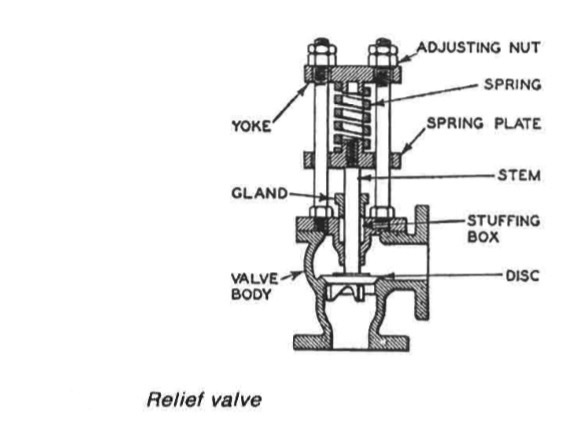
Relief Valves Pressure Reducing Valves Ship Service Systems
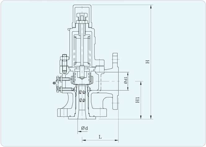
Full Bore Safety Relief Valve Ynv English

Pressure Control Valves Pressure Reducing Valve Hydraulic Schematic Troubleshooting
Relief Valve Wikipedia
Safety Valves Interesting Facts And Much More


