Charging System Wiring Diagram
Http Www Metroplexalternator Com Uploads 1 5 2 8 Charging System Theory Pdf
1998 Chevy Alternator Wiring Diagram Kenwood Kdc 252u Wiring Diagram Car Stereo For Wiring Diagram Schematics
Charging System Wiring For A Bodies Only Mopar Forum

The Main Circuit Schematic Diagram Of Charging System For Energy Download Scientific Diagram

17 Honda Gx390 Engine Wiring Diagram Engine Diagram Wiringg Net Electrical Diagram Diagram Engineering

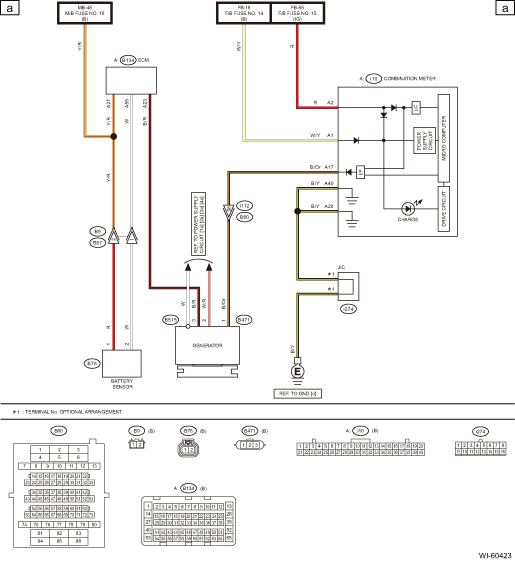
Subaru Crosstrek Service Manual Charging System Wiring Diagram Wiring System
Stator output is 37 V AC Battery voltage is 126 at idle and at speed Not sure if wiring is hioked up correct Anybody got a picture of the wiring harness connection on the right side of the engine while looking at it from the back?.
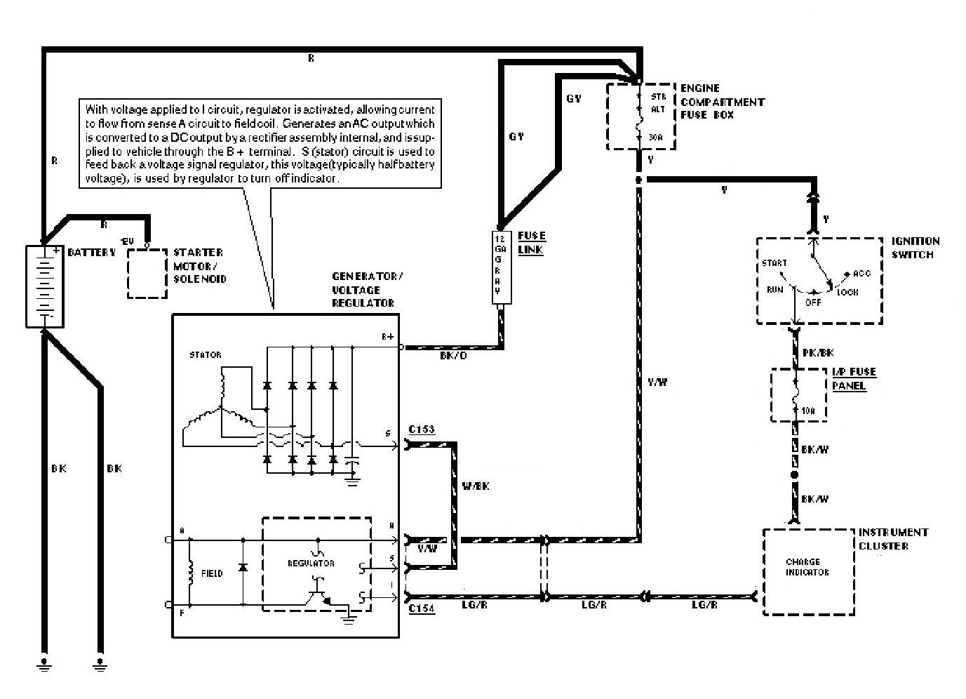
Charging system wiring diagram. Many people have spoken to me over the years about how confusing and strange their charging system wiring is on their CUCV vehicles I hope that this series of photos and information will help shed some light on the subject This first photo illustrates the wires that should terminate at your Gen2 They are as follows 1. Fig 6 1980 GMR/V Series Wiring Schematic;. Charging system problems requires a thorough understanding of the system components and their operation Operation When the engine is running, battery power energizes the charging system and engine power drives it The charging system then generates electricity for the vehicle's electrical systems At low speeds with some electrical loads "on.
Description Wiring The 25 Hp Kohler pertaining to Kohler Engine Charging System Diagram, image size 778 X 6 px, and to view image details please click the image Here is a picture gallery about kohler engine charging system diagram complete with the description of the image, please find the image you need. A typical campervan split charging system has a device that connects the battery used to start the engine to the leisure battery when the engine is running. 18 Hp Briggs Charging Wiring Diagram Diode Briggs and Stratton Charging/Electrical System Briggs 18 HP As you can see on the schematic, the 2 diodes result in a plus and a minus Briggs & Stratton engines are equipped with a number of different alternator systems to meet the require ments of.
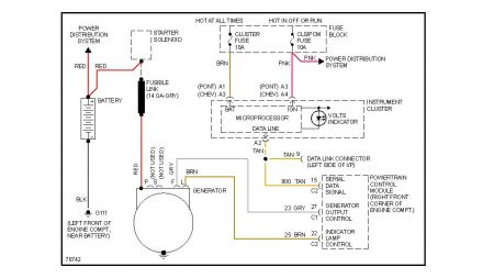
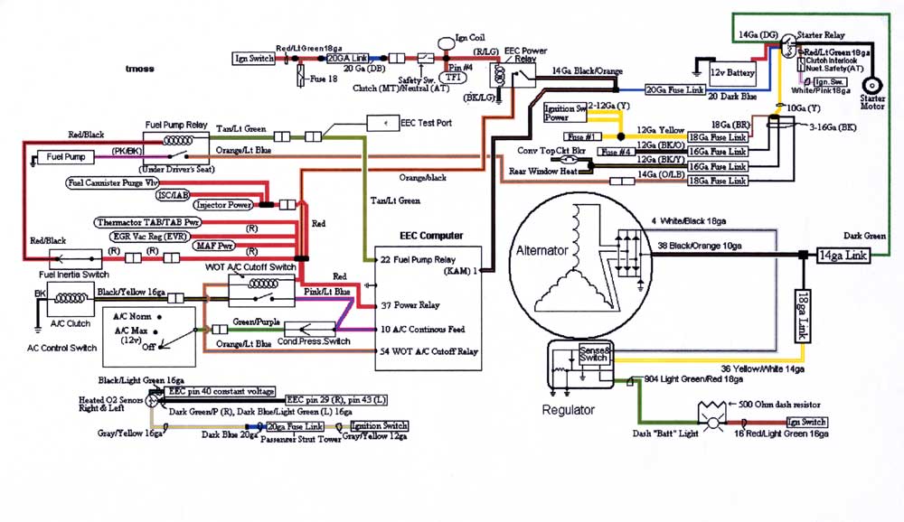
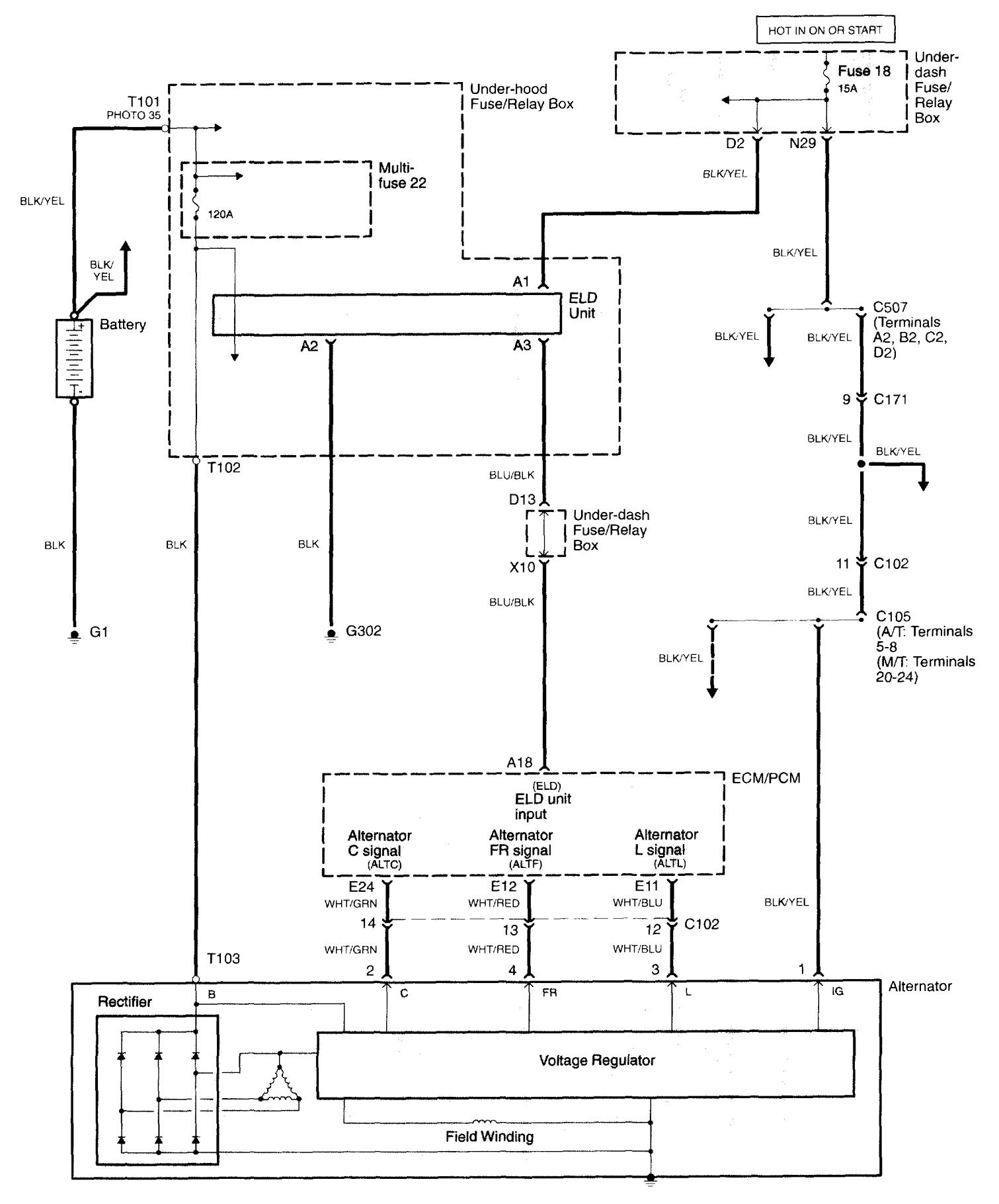
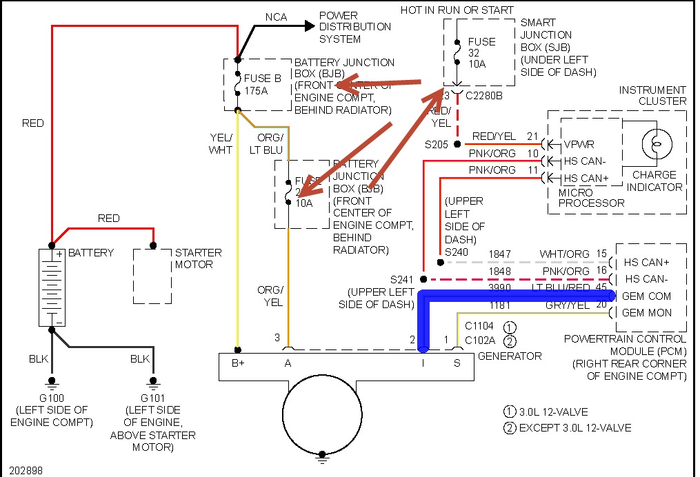
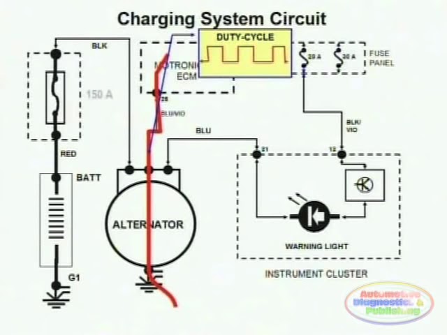
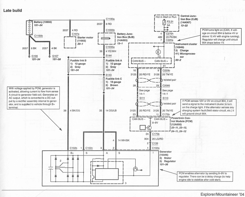
Reference the wiring diagram at the PCM We are concerned with pin 25 in the Grey C3 connector as it is the opposite end of the dark blue wire at the alternator We are also concerned with pin 10 of the White C3 connector as it is the opposite end of the green wire at the alternator. Stator output is 37 V AC Battery voltage is 126 at idle and at speed Not sure if wiring is hioked up correct Anybody got a picture of the wiring harness connection on the right side of the engine while looking at it from the back?. Some other tidbits available from AC Delco for wiring up a 10SI, is wiring package (for those 6 to 12volt conversions) This contains the terminal connector AND an extra resistance wire pigtail to connect to the ignition system (don't use a ballast resistor if you use a resistance wire) Also available is an ammeter package ().
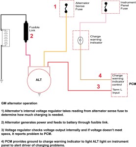
In the BAT plug two wire version, the alternator checks system voltage via a “sense” fuse located in a vehicle fuse box The whole purpose is to check voltage away from the alternator itself The reason is pretty simple;. 12 Volt Alternator Wiring Schematic Collections Of Cessna Alternator Wiring Diagram New Aircraft Alternator Wiring Wiring Diagram 12 Volt Alternator Valid Obd1 Alternator Wiring Older Alternator Wiring Diagram with Internal Regulator New 12 Volt Electrical Wiring and Charging System Help – Wiring Diagram Collection. Charging system inspection and maintenance Dirt and electrolytes between the battery terminals can cause a drain on the battery To reduce or eliminate this condition, be sure that the battery is clean Check the wiring diagram for your model year and locate the sense line to the logic module Check the voltage sense line to the logic module.
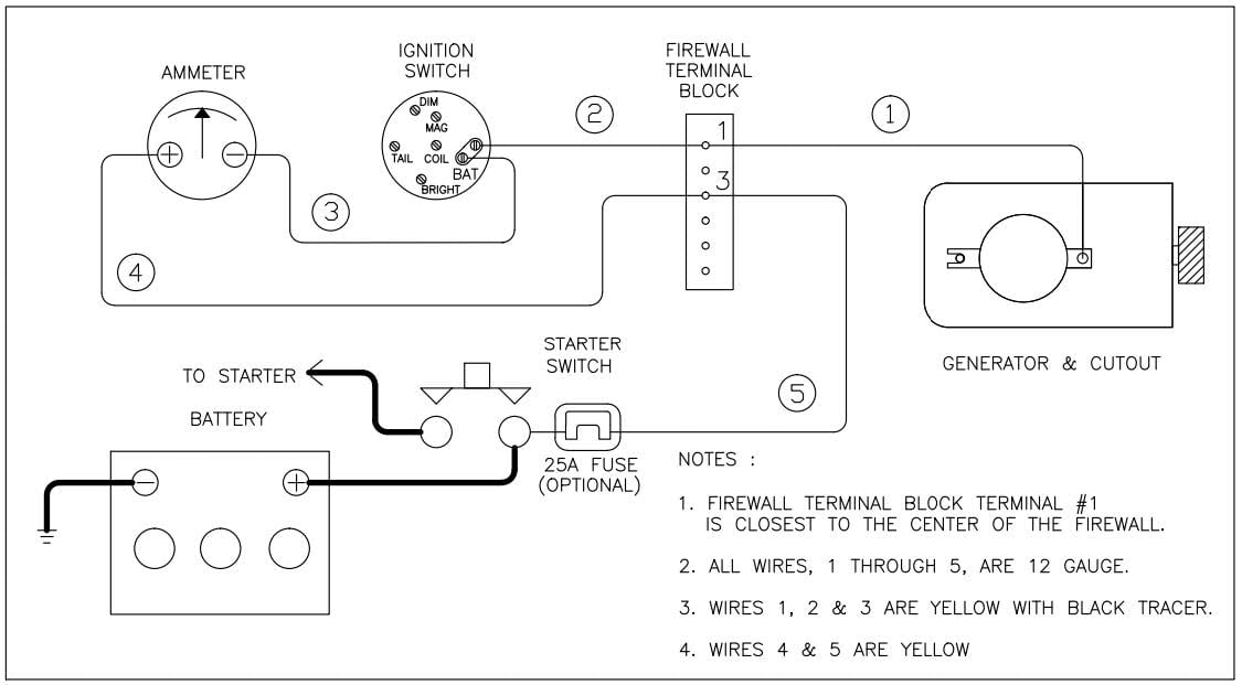
Hot Rod Wiring Diagram Please Note This diagram was designed for 12 volt systems, but can also be used for 6 volt systems If used for 6 volt, make all the wires heavier by 2 gauges For example 14 gauge wire will become 12 gauge, 10 gauge will be 8 gauge, etc. It wants to know if the charging voltage is reaching the fuse box. 8N 12 Volt Conversion Wiring Diagram 1 Wire – Wiring Diagram Explained – 12 Volt Alternator Wiring Diagram Wiring Diagram contains several comprehensive illustrations that display the link of assorted items It consists of guidelines and diagrams for various types of wiring strategies and other products like lights, home windows, etc.
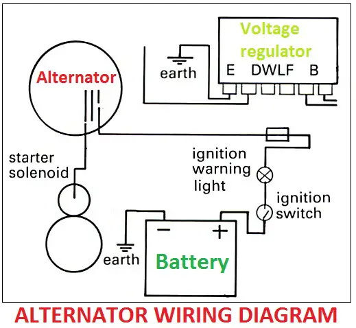
It consists of the alternator, regulator (which is usually mounted inside the alternator) and the interconnecting wiring The purpose of the charging system is to maintain the charge in the vehicle’s battery, and to provide the main source of electrical energy while the engine is running. 05 F250 is not charging the batteries Easy, it needs an alternator!. Charging System 12 Volt Alternator Wiring Diagram from ipinimgcom Effectively read a cabling diagram, one offers to know how the components inside the method operate For example , in case a module will be powered up and it sends out a signal of 50 percent the voltage in addition to the technician would not know this, he would think he.
• Systems Operation – How it works • Component Locator – Where it is • Connectors & Pinouts – What it looks like, and finally, • Subsystem Schematics – Detailed wiring and electrical schematic information WHAT’S NEW FOR THE MEDIUM DUTY C SERIES. Just got a gx engine has the 10 amp charging system and coming from fly wheel were is the rectifier located on The wiring diagram is on page parts catalog to determine the engine's charging system rated capacity Charging Page 2 of 3 • Honda Engine Charging System Charge Coil Wires Charge Coil inspection chart in the appropriate shop. The electrical system on 6 and 12volt VWs up to and including 1972 used a generator to produce power, a voltage regulator to set the charging level, and a battery to store the power The voltage regulator is used to adjust the current flowing through the field windings (the stationary outer windings) of the generator.
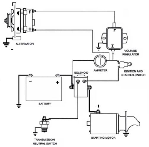
There are four basic elements to a Mustang’s charging system—battery, alternator, voltage regulator, and the wiring harness that ties it all together Before you take your Mustang’s ammeter. Mopar Wiring Diagrams 1972 to 1976 The wiring diagrams below are from various internet sources and individual contributors All diagrams are individual jpg files based on model year and vehicle 1972 Model Year 1972 Chrysler 300 & New Yorker (Schematic A). Basic Wiring Diagram For All Garden Tractors Using A Stator And – Briggs And Stratton Charging System Wiring Diagram Wiring Diagram includes many comprehensive illustrations that display the connection of varied items It includes directions and diagrams for various types of wiring strategies along with other things like lights, home windows, etc.
Charging System/Battery 151 15 Charging System/Battery Service Information 151 Troubleshooting 152 Battery 153 Charging System Inspection 153 check the wiring circuits at each terminal of the main harness coupler Inspection Items Item Judgment criteria Battery (red) Battery voltage must be. Hot Rod Wiring Diagram Please Note This diagram was designed for 12 volt systems, but can also be used for 6 volt systems If used for 6 volt, make all the wires heavier by 2 gauges For example 14 gauge wire will become 12 gauge, 10 gauge will be 8 gauge, etc. The following basic wiring diagrams show how batteries, battery switches, and Automatic Charging Relays are wired together from a simple single battery / single engine configuration to a two engine, one generator, and four battery bank system For more detailed wiring guidelines please consult a qualified marine electrician or one of the many.
A super simple wiring diagram on how a split charge device directs power towards the leisure battery one it has been engaged How does the leisure battery charge?. 6772 wiring diagram Back to FAQ Home Home. Wiring Diagrams Wiring Color Chart Misc Related Info Section I Wiring and Electrical Alternator Voltage Regulator Instrument Panel Starter and Drive Distributor Distributor Modulator System Transmission Regulated Spark System Headlamp / Parking Lamp / Taillamps Dome Lamp Mirror Lights Camper Wiring Windshield Wiper Motor You are.
Here is a basic wiring diagram that applies to all Vintage and Antique Lawn and Garden Tractors using a Stator Charging System and a Battery Ignition System We did our best to keep this as simple and as easy to understand as possible This applies to all old Cub Cadet, Ford, Jacobsen, John Deere, Wheel Horse, Case, and Simplicity Garden Tractors. Share your videos with friends, family, and the world. The following basic wiring diagrams show how batteries, battery switches, and Automatic Charging Relays are wired together from a simple single battery / single engine configuration to a two engine, one generator, and four battery bank system For more detailed wiring guidelines please consult a qualified marine electrician or one of the many.
1966 mustang stereo schematic wiring diagram 224 KB 1967 ford mustang instrument panel 256 KB 19 1985 ford ranger charging system power distribution wiring diagram 112 KB 19 19 ford ranger 28l and 29l engine ignition wiring diagram 124 KB 19 19 ford ranger exterior light diagram KB. Charging System Test Steps *** All steps must be done with a fully charged battery The engine must be running and an electrical load applied to the system (lights , etc) An Analog Voltmeter is recommended but a Digital Voltmeter will work *** Step 4 Key ON/Engine OFF Unplug alternator. New battery, 2 new alternators, new negative and positive battery cables (along with the fusible link between the pos and alternator), checked all fuses and relays in both fuse boxes (visually and with dmm), checked continuity of all cables withing the charging system, tested starter at AutoZone(passed), and recently checked both alternator and.
Nal system provided Often the equipment wiring harness is not compatible with the Briggs & Stratton alternator output harness To create a compatible system it may be necessary to modify the the equipment wiring harness To do this a wiring diagram for the equipment is essential The original keyswitch may also create a problem. Briggs And Stratton Charging System Wiring Diagram – briggs and stratton charging system wiring diagram, Every electrical arrangement consists of various unique parts Each part ought to be placed and linked to different parts in specific way If not, the structure won’t function as it should be. Kia Sorento Alternator Circuit Diagram Second Generation XM (1121) / Kia Sorento XM 1121 Service Manual / Engine Electrical System / Charging System / Alternator Circuit Diagram COM signal When controlling the voltage generated, the ECM sends the target voltage data to the alternator via a PWM signal(High voltage 4V or higher.
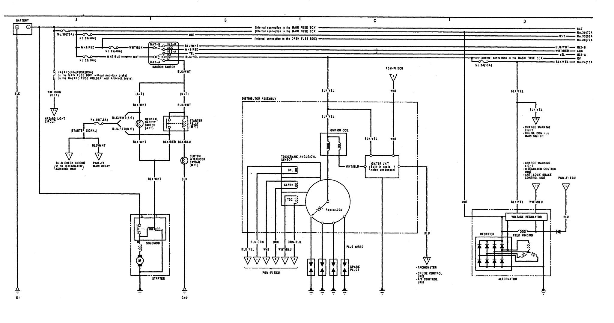
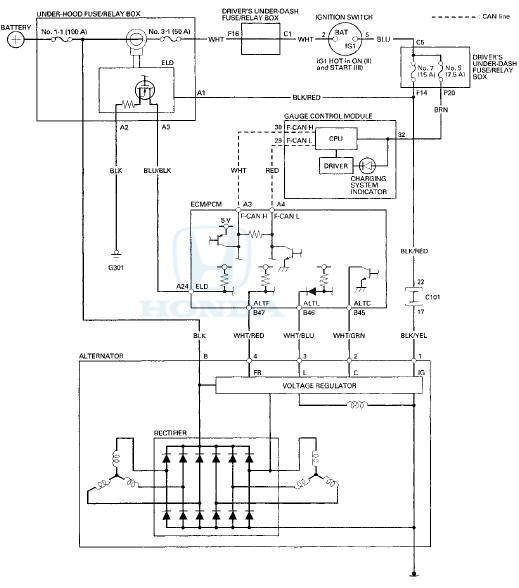
Hey guys, I've got an 84 GMC suburban K2500 4x4 J code 62 diesel I've got a weird problem and my Haynes manual doesn't have a wiring diagram of the charging system My problem is that my alternator is NOT charging. If you use a key to start your lawn mower, snow blower or outdoor power equipment, the small engine includes an electrical charging system with a battery and alternator. The charging system utilizes the L circuit to inform the driver of any charging system faults Over the years Honda has used two methods for illuminating the charge warning indicator lamp On older models, the L circuit directly provided ground for the warning lamp if a problem was present If everything was in spec, the voltage regulator.
18 Hp Briggs Charging Wiring Diagram Diode Briggs and Stratton Charging/Electrical System Briggs 18 HP As you can see on the schematic, the 2 diodes result in a plus and a minus Briggs & Stratton engines are equipped with a number of different alternator systems to meet the require ments of. Complete Charging System Wiring Diagrams page 2 How Fusible Links Work in Charging Systems with Ammeter Credits This page is an edited and shortened version of explanations and illustrations presented on several forums by mopar enthusiast who goes by screen name "NachoRT74". This page uses frames, but your browser doesn't support them.
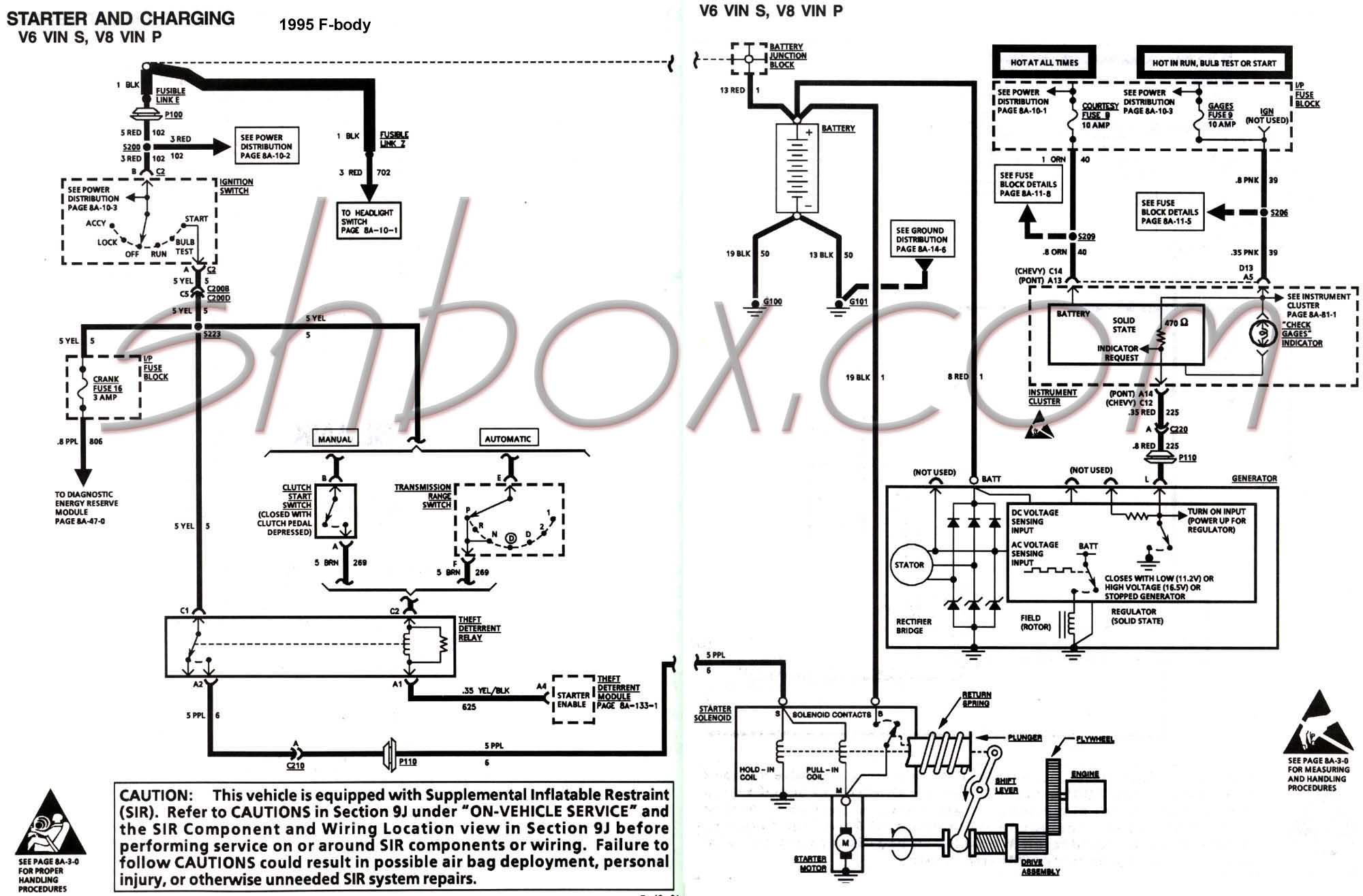
The following basic wiring diagrams show how batteries, battery switches, and Automatic Charging Relays are wired together from a simple single battery / single engine configuration to a two engine, one generator, and four battery bank system For more detailed wiring guidelines please consult a qualified marine electrician or one of the many. Fig 5 19 GMC/K Series Wiring Schematic;. Charging System & Wiring DiagramAmazon Printed Bookshttps//wwwcreatespacecom/Amazon Kindle Editionhttp//wwwamazoncom/AutomotiveElectronicDiagn.
Share your videos with friends, family, and the world. Get to Know Your Truck’s Wiring Typical electrical problems include bad batteries, alternators, and starters, along with blown fuses and bad battery cables Some wiring system issues are more complex, however open circuits, short circuits. Briggs And Stratton Charging System Wiring Diagram – briggs and stratton charging system wiring diagram, Every electrical arrangement consists of various unique parts Each part ought to be placed and linked to different parts in specific way If not, the structure won’t function as it should be.
If you haven't overhauled your VW's wiring system, it is likely the Volkswagen's wires are aged, dried out, brittle and cracked This is why we always recommend beginning your restoration project by overhauling your wiring We have created colored wiring diagrams for your convenience. It would be appreciated My wiring plugs are damaged so I can hook it either way There are three prongs on the VR. Charging System Operation 151 Figure 87 A single diode in the circuit results in halfwave rectification (Delphi Automotive Systems) voltage reverses at the start of the next rotor revolution, the current is again allowed through the diode from X to Y An AC generator with only one conductor and.
It consists of the alternator, regulator (which is usually mounted inside the alternator) and the interconnecting wiring The purpose of the charging system is to maintain the charge in the vehicle’s battery, and to provide the main source of electrical energy while the engine is running. Charging System Test Steps *** All steps must be done with a fully charged battery The engine must be running and an electrical load applied to the system (lights , etc) An Analog Voltmeter is recommended but a Digital Voltmeter will work *** Step 4 Key ON/Engine OFF Unplug alternator.
Auto Mobile Alternator Wiring Diagram Rt3 Boss Plow Wiring Diagram For Wiring Diagram Schematics
Http Www Autoshop101 Com Forms Elec05 Pdf

Lincoln Alternator Wiring Diagram

New Wiring Diagram Car Charging System Diagram Diagramtemplate Diagramsample Mitsubishi L0 Ford Mustang Mustang
Acura Integra 1991 1992 Wiring Diagrams Charging System Carknowledge Info

New Wiring Diagram Car Charging System Diagram Diagramtemplate Diagramsample Alternator Electrical Circuit Diagram Electrical Diagram

Diagram 1968 Vw Beetle Wiring Diagram Charging System Full Version Hd Quality Charging System Thezendiagram1 Hotel Du Commerce Auriol Fr

New Wiring Diagram Car Charging System Diagram Diagramtemplate Diagramsample Electrical Circuit Diagram Car Alternator Alternator
67 Alternator Not Charging Battery What S This Wire Stangnet

Electrical Winding Wiring Diagrams Old Car Alternator Wiring Diagram

Alternator Circuit Diagram Battery Charging System Components Of Alternator In Hindi Youtube

Charging System Wiring Diagram Motogurumag
Http Training Suzukiauto Co Za Sasatrainingdocs En05 engine auxiliary systems Front page Charging Pdf
Chrysler Alternator Wiring Diagram Wiring Diagram Wave Dana A Wave Dana A Bookyourstudy Fr
Ford Charging Wiring Diagrams Wiring Diagrams Join Region Tele B Region Tele B Tinchite It
Http Www Autoshop101 Com Forms Elec05 Pdf

Schematic Diagram Charging System Wiring Diagram 1995 Volkswagen Cabrio
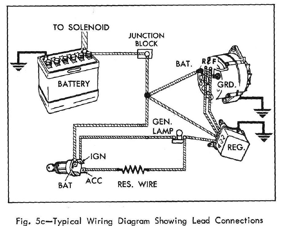
Diagram 19 Camaro Wiring Diagram Charging System Full Version Hd Quality Charging System Aurorawiring1h Dancingnevada It
Http Www Metroplexalternator Com Uploads 1 5 2 8 Charging System Theory Pdf

Training Manual
Http Training Suzukiauto Co Za Sasatrainingdocs En05 engine auxiliary systems Front page Charging Pdf
Http Training Suzukiauto Co Za Sasatrainingdocs En05 engine auxiliary systems Front page Charging Pdf

Acura Tl 07 08 Wiring Diagrams Charging System Carknowledge Info
Subaru Legacy Service Manual Charging System Wiring Diagram Wiring System

Wiring Diagrams Toyota Sequoia 01 Repair Toyota Service Blog

Solved 1998 Isuzu Trooper Need Wiring Diagram For Charging System Fixya
96 97 98 Mustang Altenator Starting And Charging System Wiring Diagram Wiring Diagram Power Cloud Power Cloud Navicharters It
Auto Mobile Alternator Wiring Diagram Rt3 Boss Plow Wiring Diagram For Wiring Diagram Schematics
Http Www Metroplexalternator Com Uploads 1 5 2 8 Charging System Theory Pdf

Wiring Diagrams Toyota Sequoia 01 Repair Toyota Service Blog

Alternator Upgrade Wiring Tips For Popular Gm Charging Systems
94 98 Mustang Alternator Starting And Charging Wiring Diagram

Ignition And Charging System Diagram Vw Dune Buggy Dune Buggy Auto Repair

Automotive Charging System Wiring Diagram Dakota Fuse Panel Diagram For Wiring Diagram Schematics
Q Tbn And9gcrx Nmuhpjbyltpbhydqauwibk4cy1hsvlmybydkdxszr1oysuu Usqp Cau
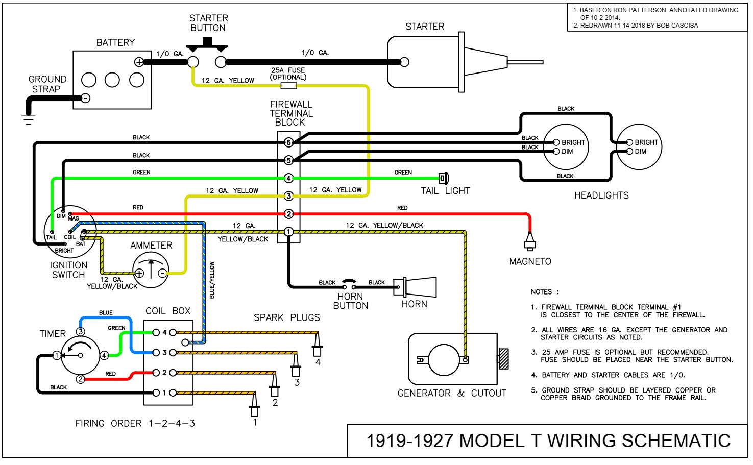
Model T Ford Wiring Diagram Telephone Intercom Wiring Diagram For Wiring Diagram Schematics

How To Wire A Motorcycle Motorcyclezombies Com

Charging System Wiring Diagram Youtube

Motorcycle Charging System Wiring Diagram 12v Wiring Schematic Diagram

New Wiring Diagram Car Charging System Diagram Diagramtemplate Diagramsample

Prestolite Leece Neville

New Wiring Diagram Car Charging System Diagram Diagramtemplate Diagramsample Autos

1990 Ford Bronco 2 Charging System Wiring Diagram Wiring Diagram Law Regulator Law Regulator Graniantichiumbri It

29 Briggs And Stratton Charging System Diagram Wiring Diagram List Briggs Stratton Stratton Electrical Diagram
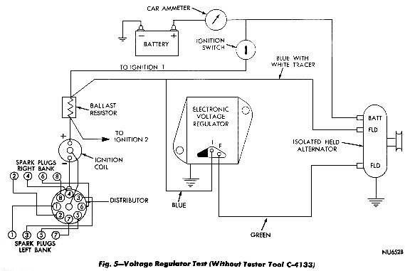
Mopar Charging Systems
Automotive Charging System Wiring Diagram Zinc Process Flow Diagram For Wiring Diagram Schematics
Acura Tl 06 Wiring Diagrams Charging System Carknowledge Info

Honda Charging Systems Auto Service World

Diagram Chevy Charging System Wiring Diagram Full Version Hd Quality Wiring Diagram Pvphasediagram Lormiservice It
Charging System Wiring For A Bodies Only Mopar Forum
Http Training Suzukiauto Co Za Sasatrainingdocs En05 engine auxiliary systems Front page Charging Pdf
Gm Alternator Wiring Ricks Free Auto Repair Advice Ricks Free Auto Repair Advice Automotive Repair Tips And How To

Circuit Diagram Of A Fundamental Battery Charging System With Input Download Scientific Diagram
Http Www Autoshop101 Com Forms Elec05 Pdf
96 97 98 Mustang Altenator Starting And Charging System Wiring Diagram Wiring Diagram Power Cloud Power Cloud Navicharters It

29 Briggs And Stratton Charging System Diagram Wiring Diagram List Briggs Stratton Stratton Briggs
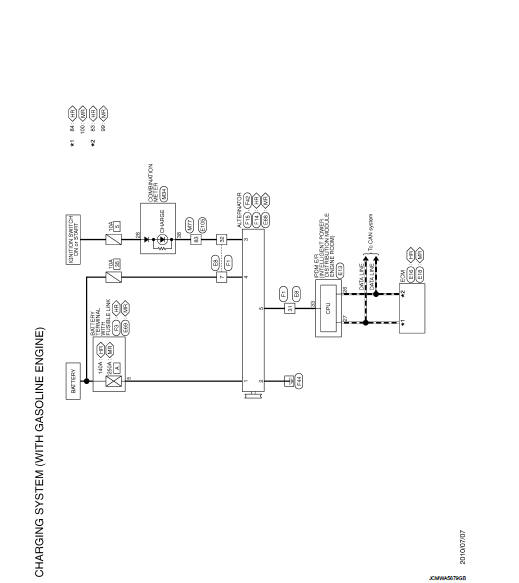
Nissan Sentra Service Manual Wiring Diagram Charging System Electrical Power Control
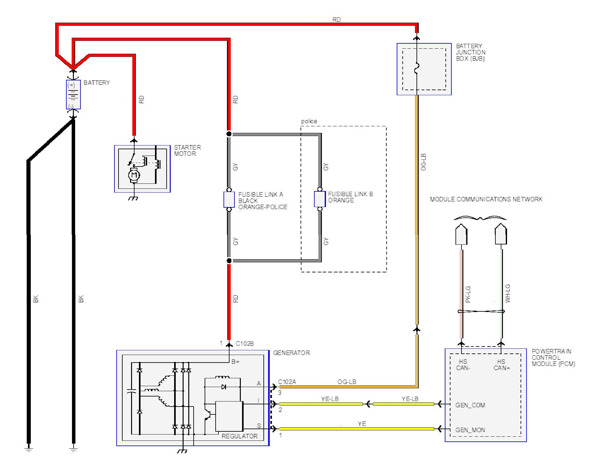
Alternator Charging System Wiring Diagrams Body Of Knowledge Powertrain Crownvic Net

Escape City Com View Topic 03 Charging System Diagram

Automotive Charging System Wiring Diagram Dakota Fuse Panel Diagram For Wiring Diagram Schematics
02 Ford Taurus Charging System Wiring Diagram 02 Ford Explorer Horn Wiring Diagram Jaguars Yenpancane Jeanjaures37 Fr

A Logical Diagnostic Process Improves Charging System Diagnosis Clore Info

New Wiring Diagram Car Charging System Diagram Diagramtemplate Diagramsample

Starting System And Charging System Wiring Diagram For Kia Pregio With Generator And Ignition Switch Or
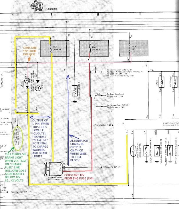
How Charging System Works 22re Yotatech Forums

Automotive Charging System Wiring Diagram Dakota Fuse Panel Diagram For Wiring Diagram Schematics
6 Volt Charging System Wiring Diagram 13 Ford Fusion Speaker Wiring For Wiring Diagram Schematics
Charging System Wiring Diagram Youtube
Wiring Diagram Charging System Nissan Juke Service And Repair Manual
Honda Accord Circuit Diagram Charging System Engine Electrical Honda Accord Mk8 08 12 Service Manual

New Wiring Diagram Car Charging System Diagram Diagramtemplate Diagramsample Alternator Electrical Circuit Diagram Electrical Diagram
Q Tbn And9gctgxjs59lk Uyqief3x2morgsnpznprvt19 M Pp5f33pswn H Usqp Cau
Http Www Metroplexalternator Com Uploads 1 5 2 8 Charging System Theory Pdf
Http Www Autoshop101 Com Forms Elec05 Pdf

04 Mustang Charging System Wiring Diagram Wiring Diagram Camp Explore B Camp Explore B Graniantichiumbri It
Alternator Charging System Wiring Diagrams Body Of Knowledge Powertrain Crownvic Net

Charging System Tests

Infiniti I35 Wiring Diagrams Car Electrical Wiring Diagram

Wiring Diagrams Toyota Sequoia 01 Repair Toyota Service Blog
Mz Alternator Charging System Diagram
Q Tbn And9gctnhtsem8awntb4sd2qxtstqh05kjq5vz0ipzua 0xmwsa0dcg0 Usqp Cau
Hyundai Santa Fe Alternator Schematic Diagrams Charging System Engine Electrical System

Charging System Wiring Diagram Youtube
Http Www Autoshop101 Com Forms Elec05 Pdf

Charging System Wiring Diagram Geo Ignition Switch Wiring Diagram Tomosa35 Jeep Wrangler Waystar Fr
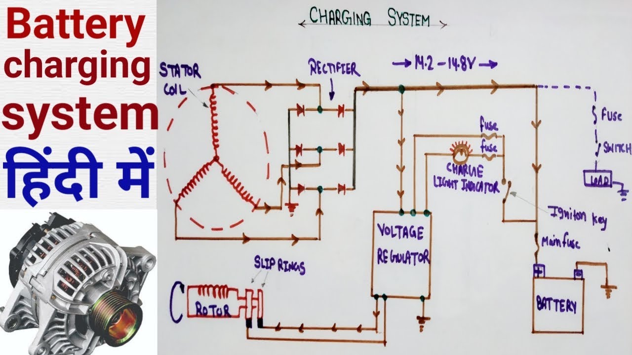
Alternator Circuit Diagram Battery Charging System Components Of Alternator In Hindi Youtube

Designed Charging Discharging Control System Wiring Diagram Download Scientific Diagram

Toyota Carina 2 Wiring Diagrams Car Electrical Wiring Diagram
3

1994 Mazda Rx 7 S At Starting System And Charging System Wiring Diagram My Blog

Simple Alternator Wiring Diagram Alternator Car Alternator Automotive Repair

I Need A Charging System Wiring Diagram For 19 Ford Econoline Van With 4 6l Six Cylinder Engine
Http Www Autoshop101 Com Forms Elec05 Pdf

Voltage Regulator Rectifier Kohler Yesterday S Tractors Electrical Diagram Engineering Kohler Engines

Auto Electrical Wiring Diagram Starting Charging System And All Lighting System Youtube
Http Training Suzukiauto Co Za Sasatrainingdocs En05 engine auxiliary systems Front page Charging Pdf
04 Explorer Charging System Failure Ford Explorer Ford Ranger Forums Serious Explorations
Circuit Diagram Of A Fundamental Battery Charging System With Input Download Scientific Diagram


